1. Analysis of embedded hardware and operating system architecture
1.1. Nordic nRF52840 SoC Hardware Architecture
1.2. Zephyr RTOS Real-Time Embedded Operating System
2. OpenThread Border Router (OTBR) Network Infrastructure
2.1. Initialize the Border Router
2.2. Synchronize network parameters (Dataset)
2.3. Terminal Routing (Commissioning)
3. Secure Authentication and Boot Mechanism with MCUboot
4. Firmware Update Procedure via MCUMGR Protocol
5. Practical Project Implementation and Hardware Ecosystem
1. Analysis of embedded hardware and operating system architecture
1.1. Nordic nRF52840 SoC Hardware Architecture
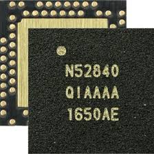
The Nordic nRF52840 microcontroller on the Seeed Studio XIAO BLE board is the optimal hardware solution for end-devices in the Smart Home ecosystem. This chipset features a 2.4 GHz multi-protocol radio transceiver, supporting both IEEE 802.15.4 (the foundation of Thread networks) and Bluetooth Low Energy (BLE). This allows programmers to use BLE to configure network commissioning via phone, then transfer data streams to the Thread network for stable operation and battery saving.
Inside the chip, the ARM Cortex-M4 (64 MHz) central processing core provides powerful performance to simultaneously run heavy protocol stacks such as OpenThread. Notably, the ARM TrustZone CryptoCell-310 hardware encryption accelerator acts as a dedicated security shield. This block automatically handles encryption algorithms (AES-CCM), data hashing (SHA-256), and digital signature authentication of MCUboot without consuming CPU resources, optimizing energy and protecting the device from the risk of hijacking or flashing pirated firmware.
1.2. Zephyr RTOS Real-Time Embedded Operating System
The nRF52840’s hardware infrastructure is managed by Zephyr RTOS – a dedicated real-time operating system for IoT systems, thanks to its flexible hardware abstraction capabilities through two tools:
- Devicetree (DTS): Describes the physical hardware structure (GPIO pins, UART, Flash partition for MCUboot) in a tree structure, allowing hardware configuration changes to be independent of the application source code.
- Kconfig: A compile-time feature selector that enables/disables software modules (e.g., CONFIG_BOOTLOADER_MCUBOOT=y) using intuitive configuration flags.
2. OpenThread Border Router (OTBR) Network Infrastructure
2.1. Initialize the Border Router
Establish a gateway to convert packets between a local IPv6 network (Wi-Fi/Ethernet) and a low-power wireless Thread network using a Raspberry Pi 5 in conjunction with the SONOFF Dongle Plus MG24 acting as a Radio Co-processor (RCP).
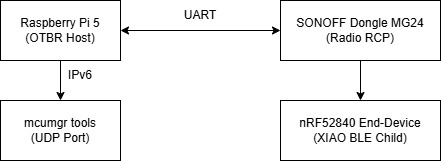
This model shows the physical connection between the Host Controller (Raspberry Pi 5) and the RCP radio circuit (SONOFF Dongle Plus MG24) via USB-UART communication.
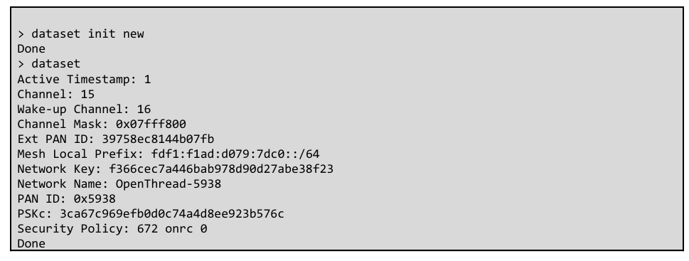
2.2. Synchronize network parameters (Dataset)
Configure the Active Dataset identifier parameters, including Network Key, PAN ID, Extended PAN ID, and Channel Mask, via the ot-ctl system controller.
2.3. Terminal Routing (Commissioning)
The process involves scanning for signals (ot discover), verifying the data configuration, and establishing the child connection state of the nRF52840 SoC (Seeed Studio XIAO BLE) into the network topology.
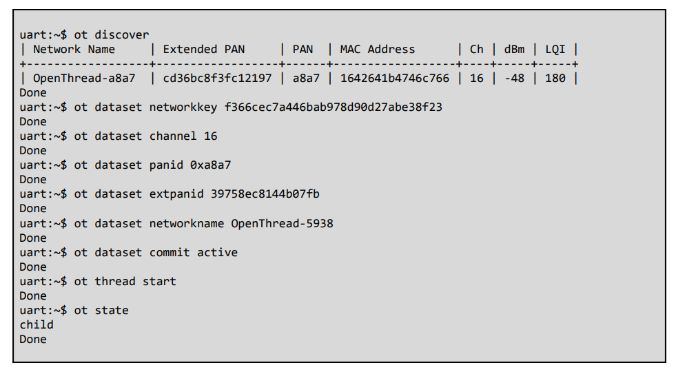
nRF52840 Thread commissioning and connection log via Zephyr Shell
3. Secure Authentication and Boot Mechanism with MCUboot
In the security architecture of IoT devices, the MCUboot acts as the first line of defense when the device is powered on. Before transferring control to the main application, MCUboot verifies the integrity and authenticity of the firmware stored in Flash memory. This process uses asymmetric encryption algorithms (such as RSA or ECDSA): MCUboot decrypts and compares the digital signature attached to the end of the application file with the public key embedded in the bootloader’s source code. If the hash (SHA-256) matches and the digital signature is valid, the device is allowed to boot; otherwise, the system will refuse execution to absolutely prevent the loading of pirated firmware or malware over the network.
To implement a system-free update mechanism and prevent circuit crashes (Anti-bricking), Zephyr RTOS uses a multi-image virtualization hardware structure via the Devicetree Overlay configuration file. This structure divides the internal Flash memory of the nRF52840 SoC into strictly functional partitions, ensuring that OTA data reception and application execution occur in two separate spaces.
┌────────────────────────────────────────────────────────┐
│ nRF52840 INTERNAL FLASH MEMORY │
├────────────────────────────────────────────────────────┤
│ boot_partition (MCUboot Bootloader) │
├────────────────────────────────────────────────────────┤
│ slot0_partition (Active Application – Primary) │
├────────────────────────────────────────────────────────┤
│ slot1_partition (OTA Download Buffer – Secondary) │
├────────────────────────────────────────────────────────┤
│ scratch_partition (Data Swap Space) │
├────────────────────────────────────────────────────────┤
│ storage_partition (Non-Volatile Storage – NVS) │
└────────────────────────────────────────────────────────┘
The system decomposes and coordinates these partitions using a secure swap mechanism:
- boot_partition: A fixed partition at the beginning of the memory range, containing the unique executable source code of the MCUboot. This memory area is configured with hardware locking to prevent any overwriting from the application layer.
- slot0_partition (Primary/Active Slot): The partition containing the currently running firmware image. The microcontroller core only reads and executes code directly from this partition.
- slot1_partition (Secondary/Upgrade Slot): A dedicated buffer partition. When the mcumgr tool performs an image upload command over the Thread network, the entire new binary file (app_update.bin) is segmented and gradually written to this partition, without affecting the application running in slot 0.
- scratch_partition: A secondary partition with a minimum size (usually the size of a Flash sector). This memory area acts as an intermediate space to temporarily back up data during the block-by-block swap process between slot 0 and slot 1 after receiving a reset command. This mechanism ensures that if the device suddenly loses power during firmware swapping, the MCUboot can still restore the data to its original state without damaging the chip.
4. Firmware Update Procedure via MCUMGR Protocol
- Network address identification: Use the End-Device’s Mesh-Local EID (IPv6) and default service port (UDP Port 1337) to establish the data transmission flow.
- The 4-step process for deploying upgrade commands via SMP (Simple Management Protocol):
- Memory status query (image list): Reads version information and hash index of the current slots on the target device.
- Segment file transfer (image upload): Pushes the digitally signed binary file (app_update.bin) into the slot1_partition buffer.
- Set test flag (image test): Marks the new partition in a temporarily pending state.
- Reboot and configuration finalization (reset & image confirm): Commands the device to reboot over the network; MCUboot performs partition swapping; after the system successfully boots on the new firmware, sends a permanent confirmation command to complete the upgrade cycle.
5. Practical Project Implementation and Hardware Ecosystem
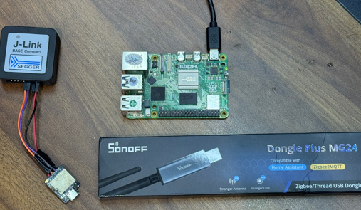
While sections 1 through 4 established the theoretical embedded, network, and security architectures, this section presents the actual physical deployment on the development test bench. Figure 5.1 showcases the integrated hardware ecosystem used for early-stage direct flashing, comprehensive debugging, and subsequent wireless secure over-the-air firmware updates via the Thread network.
Components overview:
- Host Controller (Raspberry Pi): Positioned centrally, this single-board computer is powered via USB-C. It runs the OpenThread Border Router (
ot-br-posix) stack and themcumgrtool, serving as the network gateway and update manager. - Thread RCP Dongle (SONOFF Dongle Plus MG24): Displayed in its commercial packaging (noted for “Compatible with Home Assistant,” “Zigbee2MQTT,” and “Stronger Antenna”), this USB dongle (based on Silicon Labs MG24) will be plugged into the Raspberry Pi. Crucially, it is flashed with the OpenThread Radio Co-processor (RCP) firmware to establish and lead the Thread wireless mesh.
- Debugger (SEGGER J-Link BASE Compact): A high-performance probe connected via a 4-wire SWD/JTAG debugging cable. It is used for initial non-OTA flashing (e.g., programming the MCUboot bootloader) and real-time on-chip debugging of the target device. Its compact form factor is well-suited for embedded development.
- Target End-Device (nRF52840-based board): The small, metal-shielded nRF52840 module connected to the J-Link probe via the debugging cable. This is the target node for secure OTA updates, and the connection permits RTT console monitoring and direct code execution control.
Practical hardware ecosystem deployed on a wood workbench, showcasing the Raspberry Pi Host Controller, Thread RCP Dongle, SEGGER Debugger, and nRF52840-based Target End-Device. This physical setup demonstrates the end-to-end development workflow: a developer can create code for the nRF52840 SoC, perform initial programming and comprehensive debugging via J-Link, and then transition to a secure deployment phase, managing image updates wirelessly from the Raspberry Pi over the Thread network established by the MG24 dongle, exercising the MCUboot-signed failure-safe update mechanism detailed.