1. Firmware Redundancy (FIP)
2. Configuring OTA A/B with RAUC in Yocto Project
3. Atomic Update Workflow
4. Conclusion
An embedded system not only needs to boot quickly but also must possess robust self-recovery and over-the-air (OTA) update capabilities. Integrating A/B redundancy is the gold standard to ensure the device never becomes “bricked” (unable to boot due to software failure) when an update process unexpectedly fails.
1. Firmware Redundancy (FIP)
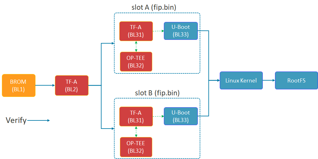
Shema of FIP
The diagram above illustrates the Chain of Trust (FIP) boot process of the STM32MP1. TF-A (BL2) plays a crucial role in selecting Slot A or Slot B to load the FIP package (including U-Boot and the secure environment) before proceeding to load the Linux Kernel.
The security of the A/B mechanism on the STM32MP1 does not begin with the Linux Kernel, but starts in the very first seconds of the boot process at the lowest Bootloader layer. This is achieved through the FIP (Firmware Image Package) structure.
- TF-A (BL2): This is the first component to run after the ROM code. BL2 acts as the verifying entity. It checks the digital signature and integrity of subsequent partitions. Most importantly, BL2 possesses the logic to choose whether to boot from Slot A or Slot B.
- FIP Container: As shown in the diagram above, each slot (A or B) is an independent fip.bin packet. Inside this container are:
- TF-A (BL31): Manages runtime security services.
- OP-TEE (BL32): Trusted execution environment, protecting sensitive tasks.
- U-Boot (BL33): The main character controlling the Kernel loading process that we optimized for speed in the previous section.
- Fail-over mechanism: If the FIP partition in Slot A fails or doesn’t pass the verification step, BL2 will automatically redirect to Slot B. This is a hardware insurance layer that ensures the device always has a chance to successfully restart.
2. Configuring OTA A/B with RAUC in Yocto Project
Based on the latest documentation from meta-rauc, we will proceed through the following steps:
Step 1: Add the necessary layers.
Open bblayers.conf and add the dependent layers:
Bash
bitbake-layers add-layer layers/meta-rauc
bitbake-layers add-layer layers/meta-openembedded/meta-filesystems
Step 2: Configure Local (local.conf)
Enable RAUC and file system support features:
Code snippet
# Enable RAUC in Distro
DISTRO_FEATURES:append = " rauc"

# Install tools RAUC into Image
IMAGE_INSTALL:append = " rauc u-boot-fw-utils"

# Request Kernel support SquashFS
KERNEL_FEATURES:append = " features/nand/nand-rauc.scc"
Step 3: System Configuration (RAUC-CONF)
Important note from the documentation: Starting with the newer Yocto (Scarthgap) version, configuration files such as system.conf and keyring must be included in a separate recipe called rauc-conf.bb.
Create file recipes-support/rauc/rauc-conf.bbappend in your layer:
Code snippet
FILESEXTRAPATHS:prepend := "${THISDIR}/files:"

# The file system.conf will be auto installed into /etc/rauc/
Step 4: Write the file system.conf for NAND
This file defines the “Slots” so that RAUC understands the partition layout on your device: Ini, TOML
[system]
compatible=stm32mp1-tcu
bootloader=u-boot
statusfile=/var/lib/rauc/status

[slot.rootfs.0]
device=/dev/ubi0_rootfs_a
type=ubifs
bootname=A

[slot.rootfs.1]
device=/dev/ubi0_rootfs_b
type=ubifs
bootname=B
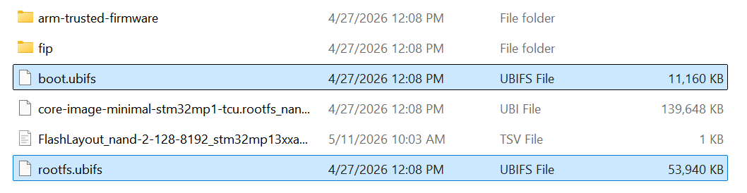
Two files, boot.ubifs and rootfs.ubifs, were created.
3. Atomic Update Workflow
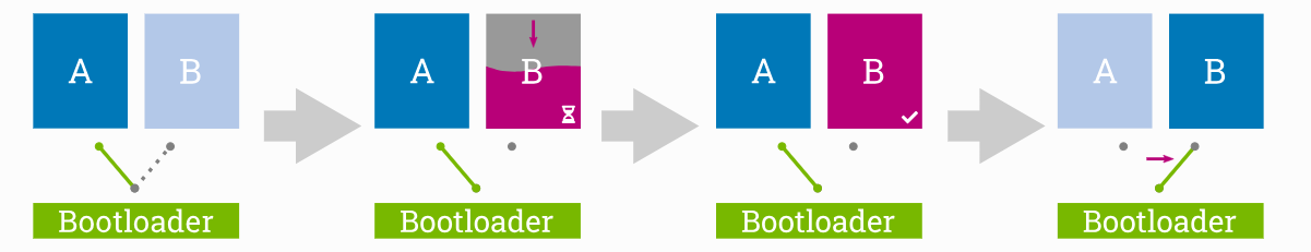
OTA’s 4-STEP PROCESS
The 4-stage update process ensures atomicity: The system only switches the boot region (Switch) to Slot B after the update has been successfully written and fully verified in the background.
The absolute advantage of the A/B Ready mechanism is its atomic update capability. This means the update process is either completely successful and verified, or nothing changes at all — absolutely no in-between state causing system errors.
This process takes place in 4 rigorous stages:
- Stage 1 (Running on A): The system is running normally on Slot A. Slot B acts as an idle memory area (Passive slot), containing an older version of the operating system.
- Stage 2 (Updating B): This is the crucial point for the user experience. The new update is downloaded and written directly to Slot B in the background. The device continues to operate normally, with no downtime during this phase.
- Phase 3 (Verify B): After writing is complete, RAUC performs a digital signature and integrity check. If data is corrupted during transmission, Slot B will be flagged as corrupted, and the system will continue to run safely on Slot A.
- Phase 4 (The Switch): After restarting, the bootloader performs an extremely fast slot switching operation based on optimized environment variables. Thanks to the system streamlining steps in Chapter 2, this “Switch” process is so smooth that users will hardly notice the system has just been upgraded to a completely new version.
4. Conclusion
The successful integration of the OTA A/B Ready mechanism is a crucial step in transforming a prototype into an industry-standard device. In summary, we have achieved:
- Superior performance: Thanks to the strategy of avoiding NAND bandwidth (Lazy Mount) and streamlining Systemd services, the device is no longer bottlenecked during boot-up, providing a smooth instant-on experience.
- High Availability: The A/B mechanism, from the FIP (Firmware) level to the OS (RAUC) level, ensures the device always has a safe exit. If an OTA update fails, the system will automatically fall back to the previous slot, completely eliminating the risk of being “bricked” on-site.
- Future-ready: With the Yocto architecture pre-configured for OTA, maintenance, security patching, and remote feature upgrades are simpler and safer than ever before.
Optimizing boot time is not just a race for numbers, but a matter of reliability. An ideal STM32MP1 system is one that boots up quickly enough to satisfy users, but is also robust enough (A/B Ready) to withstand any update risks. Hopefully, this roadmap from I/O “surgery” to OTA “Bring-up” will help you fully master ST’s powerful MPU line.