In embedded systems running Linux, the boot process is not simply a matter of turning on the power and running the operating system. Especially with the STM32MP1 processor family, the bootchain is designed as a multi-stage boot to ensure flexibility, security, and the ability to configure complex hardware.
From the moment power is applied, the system goes through a series of consecutive steps: from the internal BootROM, to a low-level bootloader like Trusted Firmware-A, followed by a high-level bootloader like U-Boot, and finally to the Linux kernel and user space. Each stage has its own role and is closely interdependent.
Understanding the bootchain is not only crucial for grasping how the system boots, but it’s also key to:
- Debug boot errors (TF-A freezes, DDR errors, kernel panics, etc.)
- Customize the system as needed (change boot mode, optimize boot time)
- Develop and integrate firmware efficiently
In this article, we will delve into each stage of the bootchain on the STM32MP1, accompanied by illustrative diagrams and detailed analysis so you can understand the entire process from power-up to Linux being ready to operate.
Why does the STM32MP1 need multi-stage boot?
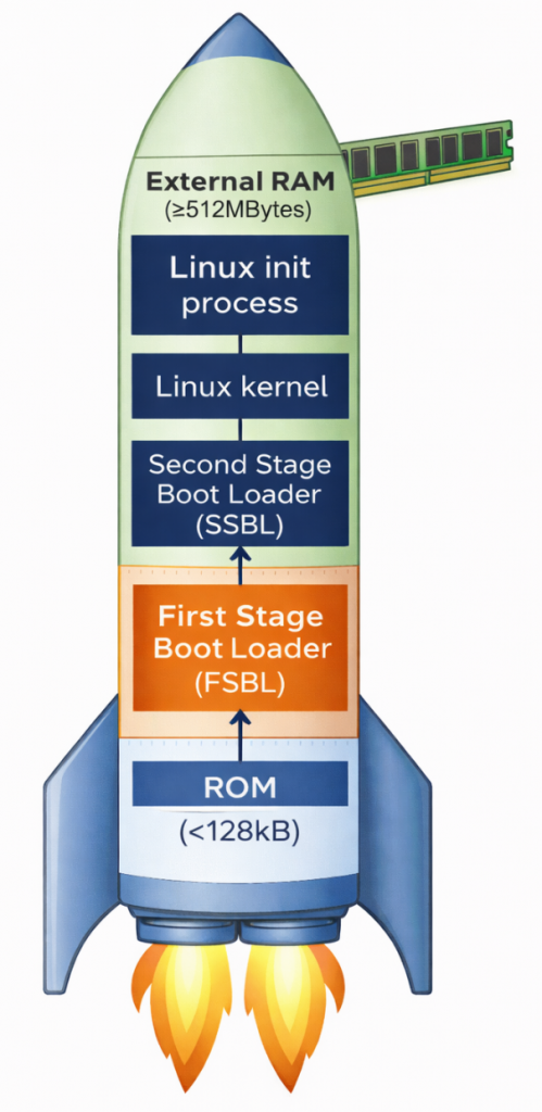
Unlike simpler microcontrollers, the STM32MP1 is a complex multi-processor unit (MPU). It requires multi-stage boot for two core reasons. First, there’s the limitation of internal memory; upon power-on, the system only has a small amount of internal SRAM (less than 256KB). This is insufficient to accommodate the entire Linux Kernel (which weighs tens of MB); therefore, intermediate steps are needed to “wake up” external RAM (DDR). Second, flexibility and security are important. Breaking down the stages allows developers to customize hardware configurations (such as RAM type and storage devices) and establish security layers (Secure Boot) before the operating system officially takes control.
Overview of the main stages:
- BootROM: Internal source code responsible for finding the first boot device.
- FSBL (First Stage Bootloader): Usually TF-A, its main task is to configure DDR RAM and set up a secure environment.
- SSBL (Second Stage Bootloader): Usually U-Boot, provides file management features and prepares the kernel loading environment.
- Linux Kernel: The heart of the operating system, managing resources and controlling peripheral devices.
- RootFS: The file system containing applications, libraries, and the end-user interface.
ROM Code

The ROM code in the STM32MP1 is immutable, meaning it cannot be changed, deleted, or overwritten by the user, thus acting as the most reliable software in the entire system. Immediately after the reset signal is released, the ROM code begins execution almost instantaneously, ensuring a fast and stable boot process. Importantly, it operates in a very limited environment – when the system has no external RAM, no high clock speed, and relies solely on the chip’s internal oscillator and SRAM to perform initial tasks.
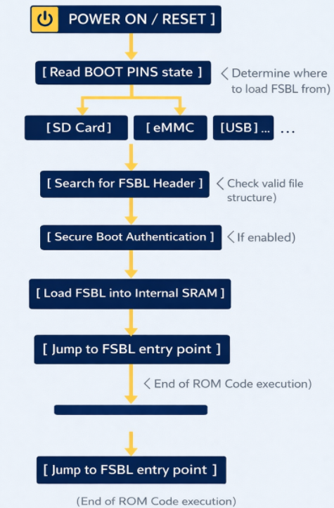
ROM Code schematic diagram
The ROM code checks the physical state (high/low) of the dedicated pins on the chip. Based on this, it knows where to find the FSBL file (SD Card, eMMC, NAND/NOR Flash, USB (DFU Mode), etc.). To read data from an SD Card or USB, the ROM code contains extremely rudimentary drivers for the SDMMC, SPI, or USB controllers. It doesn’t need an operating system; it communicates directly with the hardware at the lowest level.
The ROM code searches for a special data structure called the STM32 Header in the first bytes of external memory. This header contains information about the file size and destination address in SRAM.
If Secure Boot mode is enabled, the ROM code uses encryption algorithms (such as ECDSA) to verify the digital signature of the FSBL. If the file has been illegally modified, the chip will refuse to boot to protect the system.
After everything is valid, the ROM Code copies the entire FSBL (TF-A) file to the Internal SRAM. Then, it executes a jump instruction (Branch) to the starting address of the FSBL. From this moment on, the ROM Code “retreats” and does not participate in the operation until the next Reset.
First Stage Boot Loader (FSBL)
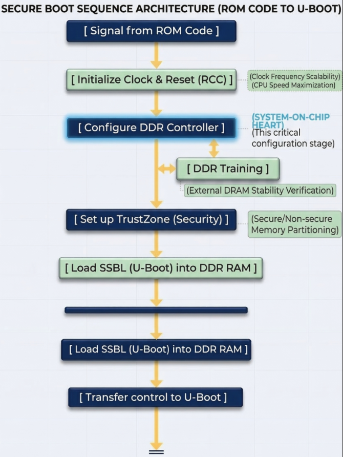
TF-A is an industry standard from ARM. It was chosen as the FSBL for the STM32MP1 because of its robust security handling capabilities and the ability to perform hardware-intensive initialization that conventional bootloaders struggle to achieve within the limited memory space of SRAM.
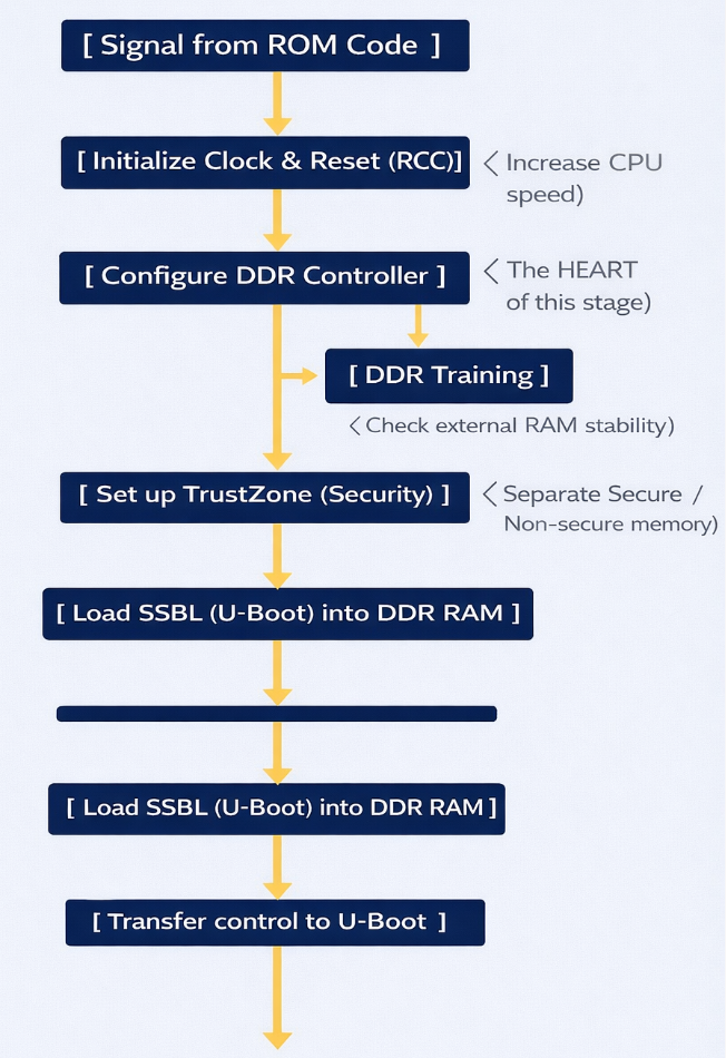
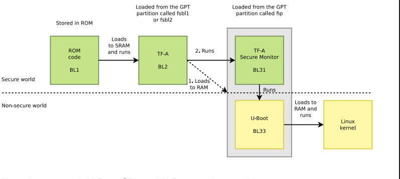
FSBL Schematic diagram
Task: (DDR Initialization) – This is the most important task. The DDR controller is an extremely complex hardware unit. The FSBL must:
- Set precise timing parameters down to the nanosecond for the type of RAM being used (DDR3, LPDDR3, etc.).
- Perform DDR Training: Send test data strings to align the signal between the chip and RAM, ensuring that data is not corrupted during high-speed transmission.
- Result: After this step, the system, which initially had only ~256KB of SRAM, can now access 512MB – 1GB of DDR RAM.
ROM Code runs at very low speeds. The FSBL will configure the power multipliers (PLLs) to push the CPU clock speed higher, allowing for faster operating system loading. It also sets up the voltage regulators (PMICs) to provide stable power to other components.
The STM32MP1 uses TrustZone technology. The FSBL is responsible for clearly defining:
- Secure World: Where sensitive tasks (encryption, digital signatures) run.
- Normal World: Where Linux and user applications run. It establishes separations to prevent Linux from illegally interfering with secure memory areas.
The FSBL runs entirely within internal SRAM. Because this space is very small, TF-A is designed in smaller “stages” like BL2. It has no user interface; you only see short logs via the serial port indicating whether the DDR initialization process was successful or failed.
Second Stage Boot Loader (SSBL)
U-Boot’s core functions:
- File System Management: This is U-Boot’s strongest point. It has drivers to understand partition formats like FAT32 or EXT4. This allows it to find the correct uImage or zImage file located deep within the memory card’s directories and load it into RAM.
- Device Tree (DTB) Usage: U-Boot not only loads the Kernel but also the Device Tree file. This is a map describing the hardware (which pins are for LEDs, which are for I2C, etc.). U-Boot can edit this map “on the fly” (while running) before delivering it to Linux, making the system more flexible.;
- Interactive Environment (U-Boot Shell): This is the only stage in the Bootchain where humans can intervene.
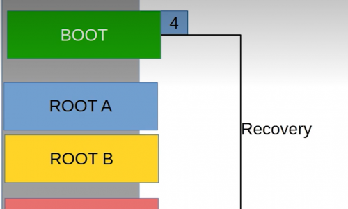
U-Boot on the STM32MP1 is usually stored in a separate partition (often named ssbl). If you want to change the boot logo or change the boot method (for example, booting over the network instead of the memory card), you just need to edit and re-flash this partition without touching the TF-A or Kernel.
Linux Kernel
Linux Kernel schematic diagram
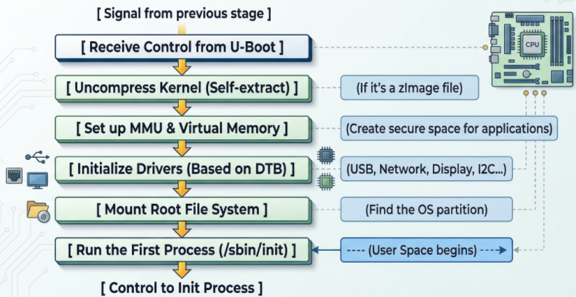
- The Linux kernel goes through several crucial steps to complete the system boot process:
First, the kernel initializes the MMU (Memory Management Unit) to convert from physical addresses to virtual addresses, isolating and protecting memory between applications, ensuring system stability even if a process fails. - Next, the kernel reads the Device Tree to load drivers and configure peripherals such as the display, network (TCP/IP for Ethernet/Wi-Fi), and industrial protocols (CAN, RS485).
- Then, the kernel attempts to mount the Root File System (rootfs) from storage devices such as SD cards or eMMCs; failure results in a “Kernel Panic” error. Upon successful mounting, the system executes the first process, /sbin/init (Systemd or BusyBox), marking the transition to User Space, where user applications begin running. Simultaneously, the kernel can also use the RemoteProc framework to load firmware and activate the Cortex-M4 core to run in parallel, handling real-time tasks while Linux processes higher-level tasks.
Linux Init process
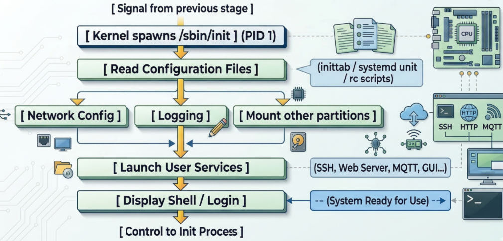
Linux Init process schematic diagram
When the kernel successfully mounts the RootFS partition (root file system), it finds and runs the first executable file. By default, this file is located at /sbin/init. The Init Process is the “parent” of all other processes in the Linux system. Its process identifier (PID) is always 1.
At this layer of the bootchain on the STM32MP1, running in user space, it executes network configuration scripts and starts applications (web server, Qt interface, or simply login commands).