1. Introduction to STM32DDRFW-UTIL
2. Overview and Download of STM32DDRFW-UTIL
3. DDR Configuration Using STM32CubeMX
4. Configuring DDR Test Firmware
5. Flashing DDR Test Firmware Using STM32CubeProgrammer
6. Running DDR Memory Tests on STM32MP135
7. Conclusion
1. Introduction to STM32DDRFW-UTIL
STM32DDRFW-UTIL is a specialized firmware utility provided by STMicroelectronics designed for the initial bring-up and validation of DDR memory on STM32MP1 series microprocessors (including STM32MP135 and STM32MP157).
This utility acts as a bridge between the hardware and the STM32CubeProgrammer interface, allowing developers to:
- DDR Initialization: Configure the DDR controller and PHY timing parameters before the bootloader (FSBL/SSBL) is even loaded.
- Configuration Validation: Verify that the DDR settings generated in STM32CubeMX match the physical RAM chip specifications.
- Comprehensive Testing: Execute built-in diagnostic routines to ensure stability: Basic Tests, quick connectivity and data bus integrity checks. Intensive Tests, deep memory cell verification to catch intermittent bit flips. Stress Tests, high-load cycles to validate Signal Integrity (SI) and thermal stability.
- Hardware Debugging: Identify PCB routing issues, impedance mismatches, or power supply V_REF / V_TT fluctuations during the board bring-up phase.
2. Overview and download of STM32DDRFW-UTIL Tool
Link download: https://www.st.com/en/development-tools/stm32ddrfw-util.html
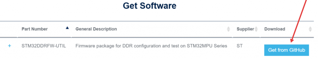
STM32DDRFW-UTIL is a toolkit provided by STMicroelectronics to support testing and evaluating the performance of DDR memory on STM32MP1 series microprocessors. This tool includes firmware tests, BSP libraries, HAL drivers, and sample projects for the STM32CubeIDE development environment. After downloading, users can build the firmware to create a .stm32 file, then flash it directly onto the board to perform RAM tests.
STM32DDRFW-UTIL offers various test types such as Basic test, Intensive test, and Stress test, allowing for testing of issues related to DDR configuration, timing, data bus, and memory stability. This enables engineers to detect hardware or configuration errors early during the bring-up process before the system boots up the bootloader or Linux operating system.
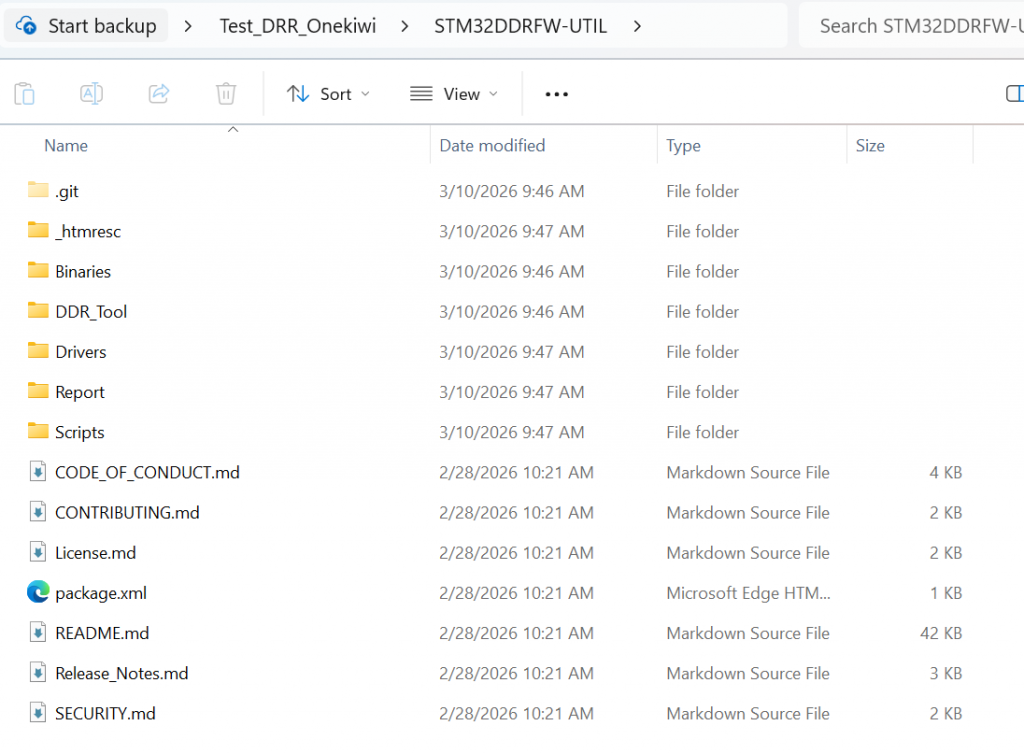
This toolkit can be downloaded directly from the STMicroelectronics development page. After downloading, users should extract the files and review the folder structure to understand the components, such as the firmware tests, sample projects, and DDR configuration files. This makes customizing the board easier and more accurate.
3. DDR Configuration Using STM32CubeMX
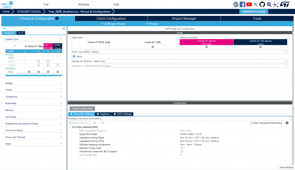
To configure DDR for the system, first open STM32CubeMX and select ACCESS TO MCU SELECTOR to search for the STM32MP135 processor. After selecting the correct MPU, create a new project. In the configuration interface, go to the System Core tab → DDR to set the memory parameters. Here, you need to select the correct type of RAM being used, for example, DDR3L Zentel A3T4GF40BBF. Next, switch to the Clock Configuration tab to configure the clock speed for the DDR controller. Set the value PLL2R = 533 MHz, which is the operating frequency of DDR. After completing the configuration steps, switch to the Project Manager tab and select GENERATE CODE to generate the source code. When the generation process is complete, access the folder …/<project_name>/DeviceTree/<project_name>/tf-a/ and find the stm32mp13-mx.dtsi file. This is a crucial file containing the complete configuration of DDR registers, used in the initialization and control of DDR memory on the system.
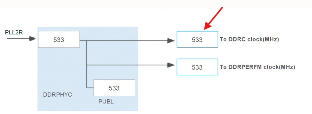
setting frequency in clock configuration
4. Configuring DDR Test Firmware
To configure the server firmware for DDR testing, first open STM32CubeIDE and import the project template STM32MP135C-DK. This is the project template provided for running the DDR Test Tool on the STM32MP135 processor line. After importing the project, it is necessary to check and adjust the PMIC configuration to match the board’s hardware. On the ST reference board, the system uses STPMIC with an I2C address of 0x33. However, for board customizations, the PMIC may be different, for example, using MP5470 with an I2C address of 0x11. Therefore, it is necessary to edit the corresponding parameters in the project’s configuration file, specifically stm32mp13xx_disco_bus.h and stm32mp13xx_util_conf.h, to ensure the firmware can correctly communicate with the PMIC and provide the correct level of power for DDR during testing.
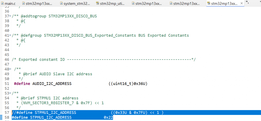
Refer to line 57 in stm32mp13xx_disco_bus.h
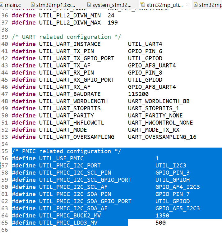
Change param in stm32mp_utils_conf.h
The following functions in main.c need to be modified: The SystemPower_Config() function is responsible for initializing the I2C interface to communicate with the PMIC and provide power to the RAM. While the STM32MP135C-DK performs strict checks, such as verifying the PMIC version, these steps are unnecessary for the Onekiwi board since it does not use an official ST PMIC. Therefore, these validation steps should be bypassed.
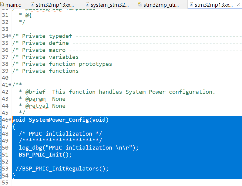
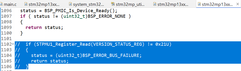
Comment out code in BSP_PMIC_Init()
The RAM configuration is handled in stm32mp13xx-ddr3-4Gb-template.h. Copy the contents of the stm32mp13-mx.dtsi file (generated from the previous RAM configuration step) and paste them into this header file. Once the configuration is accurately adjusted for the board, build the project and proceed to flash it onto the board.
5. Flashing DDR Test Firmware Using STM32CubeProgrammer
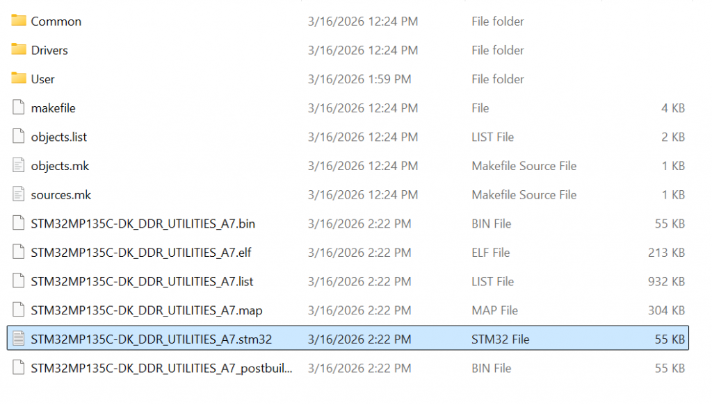
After the project build is complete in STM32CubeIDE, the system will create a firmware file in .stm32 format. This file is used to load the DDR Test Tool program onto the STM32MP135 microcontroller for RAM testing. Before flashing the firmware, connect the board to the computer via the USB Type-C port. Simultaneously, open a terminal, such as MobaXterm, to monitor logs from the board’s UART port during the tool’s execution. Next, use STM32CubeProgrammer to load the firmware. Open the CMD window and run the command: STM32_Programmer_CLI.exe -c port=USB1 -w “path_to_file.stm32” 0x01 -s 0x01
Ex: STM32_Programmer_CLI.exe -c port=USB1 -w “C:\Users\Admin\workspace\STM32DDRFW-UTIL\DDR_Tool\STM32MP135C-DK\STM32MP135C-DK_DDR_UTILITIES_A7\DK\STM32MP135C-DK_DDR_UTILITIES_A7.stm32” 0x01 -s 0x01
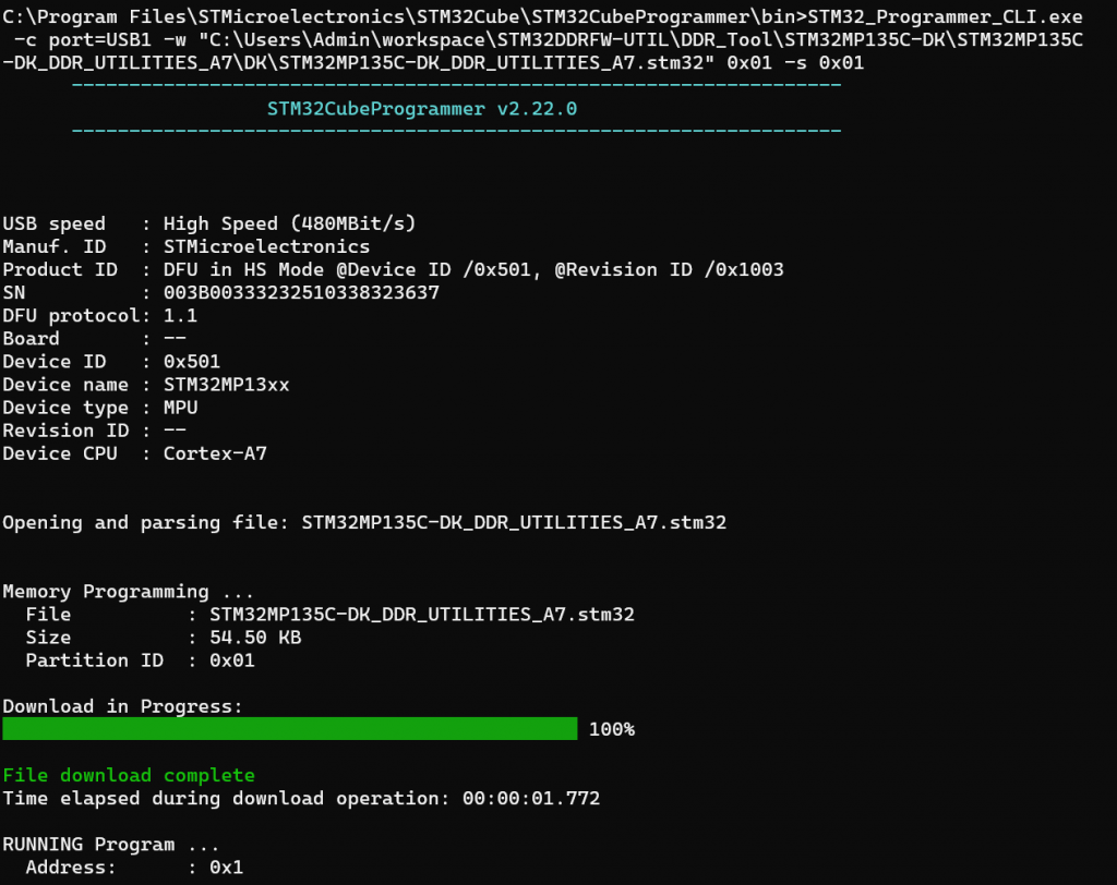
In this command, the “-w” parameter specifies the path to the newly built .stm32 file. After the command is successfully executed, the DDR test firmware will be loaded into the MPU, and the system will start running the DDR Utility Tool, ready to perform RAM testing commands.
6. Running DDR Memory Tests on STM32MP135
After the firmware is loaded and starts running on the STM32MP135, the MobaXterm terminal window will display a command prompt as shown in the image:
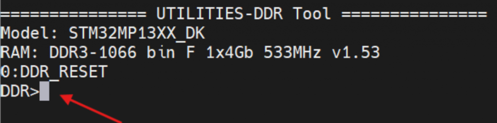
This prompt indicates that the DDR Utility Tool has successfully started and is ready to receive commands from the user. Here, you can enter commands to test and evaluate the performance of your DDR memory. For example, enter the command:
help

info

freq

...
To display a list of supported commands in the tool. Through these commands, users can view DDR configuration information, change parameters, and run RAM tests to confirm stable memory operation on the system. You can test using the following commands:
- Command info:
| Command-line | Expected result | Verdict |
|---|---|---|
| info | step = 0 : DDR_RESET | PASS |
| name = DDR3-1066/888 bin G 1x4Gb 533MHz v1.45 | ||
| size = 0x20000000 | ||
| speed = 533000 kHz | ||
| cal = 0 |
- Command freq:
| Command-line | Expected result | Verdict |
|---|---|---|
| freq | DDRPHY = 528000 kHz | PASS |
- Command param:
| Command-line | Expected result | Verdict |
|---|---|---|
| param | ==ctl.static== | PASS |
| mstr = 0x00040401 | ||
| mrctrl0 = 0x00000010 | ||
| mrctrl1 = 0x00000000 | ||
| derateen = 0x00000000 | ||
| derateint = 0x00800000 | ||
| pwrctl = 0x00000000 | ||
| pwrtmg = 0x00400010 | ||
| hwlpctl = 0x00000000 | ||
| rfshctl0 = 0x00210000 |
- Change parameter DDR:
| Command-line | Expected result | Verdict |
|---|---|---|
| param mstr | mstr = 0x00040401 | PASS |
| param mstr 0x00040402 | mstr = 0x00040402 | PASS |
| param mstr | mstr = 0x00040402 | PASS |
| param mstr 0x00040401 | mstr = 0x00040401 | PASS |
- State transition DDR:
| Command-line | Expected result | Verdict |
|---|---|---|
| next | 1 : DDR_CTRL_INIT_DONE | PASS |
| step 3 | step to 3 : DDR_READY | PASS |
| 1 : DDR_CTRL_INIT_DONE | ||
| 2 : DDR_PHY_INIT_DONE | ||
| 3 : DDR_READY |
- Command test RAM
| Command-line | Expected result | Verdict |
|---|---|---|
| test help | displays test commands | PASS |
| 0 : Test All | ||
| 1 : Test Simple DataBus |
- Test Data Bus
| Command-line | Expected result | Verdict |
|---|---|---|
| test 1 0xc0000000 | Result: Pass [Test Simple DataBus] | PASS |
- Test RAM
| Command-line | Expected result |
|---|---|
| test 0 | result 1: Test Simple DataBus = Passed |
| result 2: Test DataBusWalking0 = Passed | |
| result 3: Test DataBusWalking1 = Passed | |
| result 4: Test AddressBus = Passed | |
| result 5: Test MemDevice = Passed | |
| result 6: Test SimultaneousSwitchingOutput = Passed | |
| result 7: Test Noise = Passed | |
| result 8: Test NoiseBurst = Passed | |
| result 9: Test Random = Passed | |
| result 10: Test FrequencySelectivePattern = Passed | |
| result 11: Test BlockSequential = Passed | |
| result 12: Test Checkerboard = Passed | |
| result 13: Test BitSpread = Passed | |
| result 14: Test BitFlip = Passed | |
| result 15: Test WalkingZeroes = Passed | |
| result 16: Test WalkingOnes = Passed | |
| Result: Pass [Test All] |
7. Conclusion
The STM32DDRFW-UTIL toolkit provides an efficient and practical method for validating DDR memory during the early hardware bring-up stage of STM32MP135 and other STM32MP1 microprocessors from STMicroelectronics. By allowing developers to initialize DDR, verify configuration parameters generated by STM32CubeMX, and execute multiple memory diagnostic tests, the tool helps ensure that the DDR subsystem operates reliably before the system boots the bootloader or Linux operating system.
Through built-in commands and comprehensive testing routines—ranging from simple data bus verification to full stress testing—engineers can quickly identify potential issues such as incorrect DDR timing parameters, signal integrity problems, PCB routing errors, or unstable power supply conditions. This greatly simplifies the debugging process and reduces development time during the hardware validation phase.
In summary, integrating STM32DDRFW-UTIL into the development workflow enables engineers to confidently validate DDR hardware and configuration, ensuring a stable foundation for the entire embedded software stack.