1. Introduction to TLV320AIC3254 Linux Audio Driver
1.1. Purpose of the TLV320AIC3254 Codec Driver
1.2. Scope and Out-of-scope Features
2. System Overview for TLV320AIC3254 Audio Codec
2.1. Hardware Architecture Overview
2.2. Functional Role of Each System Component
3. Linux Audio Software Architecture (ALSA SoC)
3.1. Audio Data Path in ALSA ASoC Framework
3.2. Audio Control Path (Mixer, Codec, Registers)
4. Linux Kernel Configuration for TLV320AIC3254
4.1. Enable Subsystem in Defconfig
4.2. Disable Audio flag check (AUDIO_ENABLE_FILE)
4.3. Add support Sound Card into Build System
5. Device Tree Integration for TLV320AIC3254
5.1. Declare I2C Controller and Codec Node
5.2. Declare Regulator (Source)
5.3. Declare Sound Card (MDM9607 Audio Common)
6. Verify Driver TLV320AIC3254 Driver Operation
6.1. Checking Sound Card Registration
6.2. Testing Audio Playback Using WAV Files
1. Introduction to TLV320AIC3254 Linux Audio Driver
1.1. Purpose of the TLV320AIC3254 Codec Driver
This document is compiled to provide in-depth technical guidance on the integration (porting) and activation (bring-up) process of the TI TLV320AIC3254 audio codec chip on the Cavli C10QM module platform (based on the Qualcomm MDM9607 chipset) running the Linux operating system.
The C10QM module is designed with a digital audio interface (DAC/ADC) and does not include an integrated analog-to-digital converter (DAC/ADC) for analog-to-digital audio applications; the integration of a codec is required to support voice and music playback features.
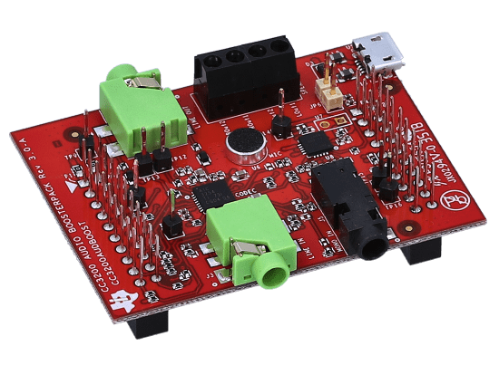
Within the scope of this guide, the CC3200 Audio Boost board is used as the reference hardware (Reference Hardware). However, it should be noted that the CC3200 microcontroller on this board will be disabled or ignored (ignored). The C10QM module will act as the host/master device, fully responsible for:
- Data flow management (Data path): Transmitting/receiving PCM audio data via the I2S/MI2S interface.
- Control management (Control path): Configuring the codec’s registers, clock, and power via the I2C interface.
This document will focus on addressing the following core technical issues:
- Software Architecture: Understanding the ALSA audio subsystem (Advanced Linux Audio Architecture) and the ASoC framework (ALSA System on Chip) on the Qualcomm platform.
- Kernel Configuration: Guidance on selecting and compiling necessary drivers (Machine Drivers, Platform Drivers, Codec Drivers).
- Device Tree Integration (DTS): Declaring hardware, configuring GPIO pin muxing, regulators, and clocks for the system to control device recognition actions.
- Testing and Verification: Using non-user-space tools such as tinyalsa and amixer to test audio paths and signal quality.
1.2. Scope & Out-of-scope Features
To ensure the focus and efficiency of the integration process, this document clearly defines the following work items: within the scope of implementation and outside the scope of implementation.
In Scope:
- Hardware Communication Setup: Instructions for connecting and configuring the physical interface between the C10QM and the TLV320AIC3254, including the MI2S data bus (MCLK, BCLK, WCLK, DIN, DOUT) and the I2C control bus.
- Driver Development and Integration: Activating the driver for the TLV320AIC32x4 codec in the Linux Kernel. Declaring a virtual Sound Card in the Device Tree to link the DAI (Digital Audio Interface) CPU and the DAI Codec.
- Audio Routing Configuration: Using kcontrols (Mixer controls) to set the signal path within the Codec (e.g., routing from DAC to Headphone Output).
- Playback Feature: Focuses on enabling PCM audio output to the headphone jack (3.5mm) in Stereo mode.
Out of Scope:
- Advanced Digital Signal Processing (DSP): Does not mention acoustic echo cancellation (AEC), noise suppression (NS), or audio effects (EQ, 3D) on Qualcomm’s Hexagon DSP.
- Application Layer Encoding/Decoding: Does not include integration of decoding libraries for compressed formats (MP3, AAC, Opus, OGG…). The document only covers playback of .wav files (raw PCM).
- Firmware Development for CC3200: Does not include any source code or configuration for the CC3200 MCU chip.
- Analog Circuit Design: Does not delve into the design of filters, capacitors, or analog amplifier circuits. It is assumed that the CC3200 Audio Boost hardware is electrically sound.
- VoLTE/CSFB Call: This document focuses on the System Audio path and does not include detailed configuration for voice stream during mobile network calls.
2. System Overview for TLV320AIC3254 Audio Codec
2.1. Hardware Architecture Overview
The system is built on a Host-Codec model, where the C10QM acts as the master device controlling all operations, and the CC3200 Audio Boost acts as an expansion board providing an analog audio interface. The connection between the two components is based on two industry-standard physical interfaces:
Data Link – Interface MI2S
- Protocol: Uses the MI2S (Multi-channel Inter-IC Sound) standard, also known as Primary I2S.
- Function: Responsible for transmitting raw PCM audio data in real time.
- Data direction: The audio system is designed to operate in full-duplex mode, allowing simultaneous playback and capture on the same I2S/PCM physical interface. Although sharing a common clock bus, the data of these two streams travels on separate signal lines, ensuring no signal interference and supporting independent debugging for each communication direction:
Playback (DL):
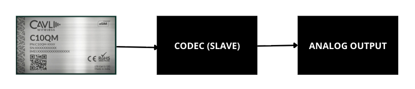 For downlink, audio data travels from the host device to the peripheral device. Specifically, digital PCM data is output by the C10QM module’s CPU via the PCM_DOUT pin (Pin 48). This signal enters the DIN pin of the TLV320AIC3254 codec. Here, the codec processes the signal through an interpolation filter and a digital-to-analog converter (DAC) to convert it into analog signal. The final signal is then passed through the amplifier (Headphone Driver) and output to the 3.5mm jack. Software-wise, the DAPM (Dynamic Audio Power Management) path is routed from the “Left/Right DAC” through the corresponding mixers to the HPL/HPR output.
Capture (UL):
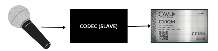 In contrast to the transmission stream, the uplink stream is responsible for bringing the signal from the environment into the processing system. The analog signal from the microphone enters the analog input of the codec, is amplified by the PGA (Programmable Gain Amplifier), and converted to digital via the ADC. The digital data is then output from the DOUT pin of the codec and goes to the PCM_DIN pin (Pin 47) of the C10QM module. At the C10QM side, the CPU receives this data stream to perform recording or processing for voice calls.
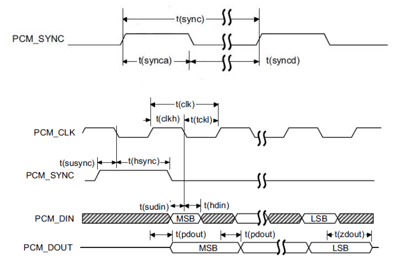
- Clocking:
The C10QM operates in Master mode, responsible for providing critical clock signals (MCLK, BCLK, WCLK) to synchronize the data sampling of the Codec. The stable operation of both data streams depends entirely on the clocking mechanism, with the C10QM acting as the master device. The C10QM module is responsible for generating and maintaining two crucial signals: the Bit Clock signal (PCM_CLK) on pin 49 to synchronize each data bit, and the Frame Sync signal (PCM_SYNC) on pin 46 to mark the start of the audio frame. Loss of either of these clock signals will cause both transmission and reception to stop immediately.
Control Link – Interface I2C
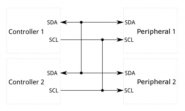
The I2C interface acts as the “command center” of the audio system, operating in parallel but completely separate from the audio data stream. While the MI2S interface is responsible for transporting digital signals (PCM), the I2C (Inter-Integrated Circuit) protocol is used specifically to configure and monitor the operating status of the Codec chip. Here, the C10QM module acts as the master device, sending read/write commands to the registers of the TLV320AIC3254 to perform complex control tasks:
- Power Management: Controls the power supply or power off for specific functional blocks within the Codec (such as turning off the ADC block when only listening to music, or turning on the Mic-Bias block when recording) to optimize power consumption for the device.
- Clocking System Configuration: Set parameters for the phase-locked loop (PLL) and internal dividers, ensuring the codec can generate standard sampling frequencies (such as 44.1kHz, 48kHz) from the original MCLK clock provided by the C10QM.
- Audio Routing: Control the internal switch matrix of the codec to determine the signal path, for example, connecting the signal from the DAC to headphones or transferring the signal from the microphone to the ADC converter.
- Signal Conditioning: Set digital volume levels, configure the analog gain for the microphone to avoid distortion, and configure audio filters if available.
2.2. Functional Role of Each System Component
Module Cavli C10QM (Follow Qualcomm MDM9607 SoC)
Acting as the Audio Master and considered the central controller of the system, this component operates on an embedded Linux operating system using the ALSA (Advanced Linux Sound Architecture) audio architecture. It integrates machine-level and platform-level drivers to manage all communication with the hardware. Core tasks include initiating the I2C protocol to activate (‘wake up’) and load configuration for the Codec at boot time, managing the audio buffer and controlling DMA to transmit PCM data over the MI2S interface, and providing the essential base clock (MCLK) source to ensure the Codec operates synchronously.
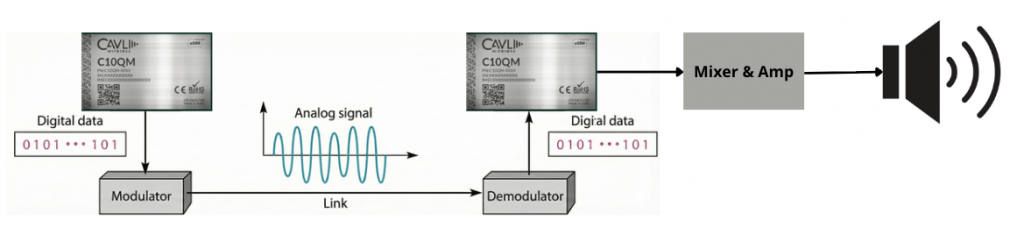
Chip Codec TI TLV320AIC3254
- Features: A low-power stereo audio codec with an integrated miniDSP.
- Main functions: DAC (Digital-to-Analog Converter): Receives digital signals from the C10QM, converts them into analog signals for headphone output; ADC (Analog-to-Digital Converter): Receives electrical signals from the microphone, converts them into digital signals to send back to the C10QM; Mixer & Amp: Mixes signals and amplifies power to drive headphones or external speakers.
CC3200 Audio Boost (Hardware Carrier)
- Function: Provides the electrical infrastructure for the Codec to operate (power supply, filter capacitors, 3.5mm jack, connector header).
- Special Note (Hardware Bypass): By default, this board is designed to work with the CC3200 MCU. In this integration guide, the CC3200 MCU on the board will be completely disabled, and the I2S and I2C signal lines of the Codec (which are connected to the CC3200 MCU) will be disconnected and directly connected (Jump wiring) to the corresponding GPIO pins on the C10QM module. This turns the CC3200 Audio Boost into a pure “Breakout board” for the TLV320AIC3254 chip.
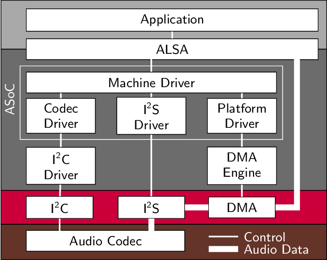
3. Linux Audio Software Architecture (ALSA ASoC)
The audio system on the C10QM (MDM9607) is built on the ALSA System on Chip (ASoC) architecture. This is a standard framework in the Linux kernel designed specifically for embedded systems, separating the SoC control code, codec, and motherboard (machine) for easier reuse.
3.1. Audio Data Path in ALSA ASoC Framework
This is the journey of audio data from a music file to the user’s headphones. The data stream processing (Playback Flow) process occurs as follows:
- User Space (Application Layer): Tools like tinyplay, aplay, or Android Audio HAL read data from the music file (wav, pcm).
- ALSA PCM Interface: Data is pushed down to the kernel via the standard PCM interface (/dev/snd/pcmCxDxp). Here, ALSA manages the Ring Buffer.
- Platform Driver (SoC DMA/DSP): On the Qualcomm MDM9607 chip, data is not directly pushed to the I2S pin by the CPU. Instead, it is transferred to the digital signal processing unit (DSP/LPASS) via DMA.
- CPU DAI (Digital Audio Interface): The I2S interface on the SoC (Primary MI2S) receives data from memory and outputs digital signals (MCLK, BCLK, WS, DATA) externally.
- Codec DAI: The TLV320AIC3254 chip receives I2S signals.
- Codec Processing: Inside the codec, data passes through an interpolation filter, a DAC (Digital-to-Analog) converter, and an amplifier (Amp).
- Analog Output: The analog signal is output to the headphone jack.
3.2. Audio Control Path (Mixer, Codec Registers)
In parallel with the data line, the control line is responsible for hardware configuration. It does not carry audio signals.
- Physical protocol: Uses I2C bus.
- Kernel mechanism: Codec drivers register kcontrols (Kernel Controls) with the ALSA Core.
- Task performed:
- Power Management (DAPM): Automatically turns on/off the power to the blocks (DAC, ADC, Amp) when there is/is not an audio stream to save power.
- Register Config: Configures the PLL registers to create the clock and the Volume register to adjust the volume.
4. Linux Kernel Configuration for TLV320AIC3254
To enable drivers and the audio system on the C10QM, changes to the kernel configuration and build system are required.
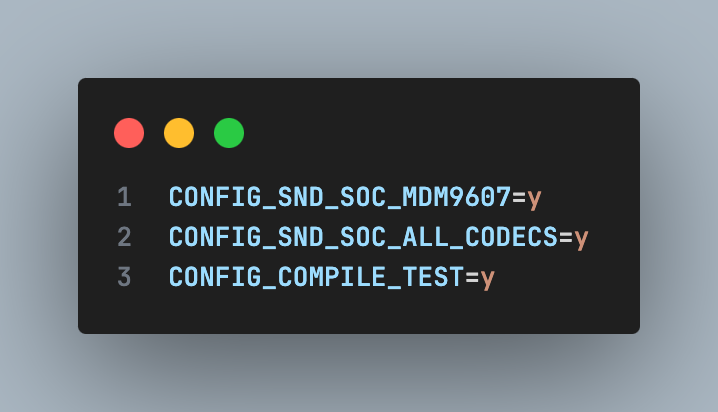
4.1. Enable Subsystem in Defconfig
Change file .config mdm9607-perf_defconfig (c10qm_linux_4/build/c10qm/eaj_v3.2/linux_change/v2/) and add infomation into Makefile:
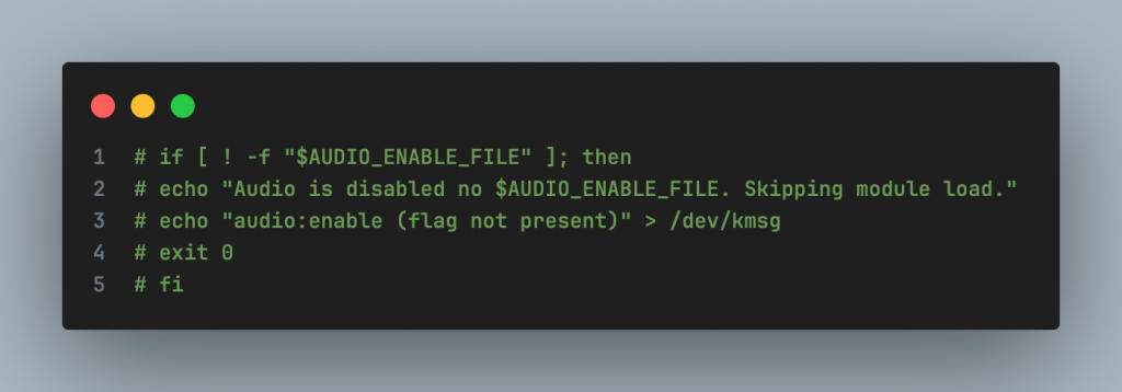
4.2. Disable Audio flag check (AUDIO_ENABLE_FILE)
To prevent the audio module from being skipped during startup, the startup script needs to be modified start_audio_le (path: apps_proc/poky/meta-qti-bsp/recipes-multimedia/audio_dlkm_kernel/files/mdm9607/).
You need to comment (disable) the coding file check flag as:
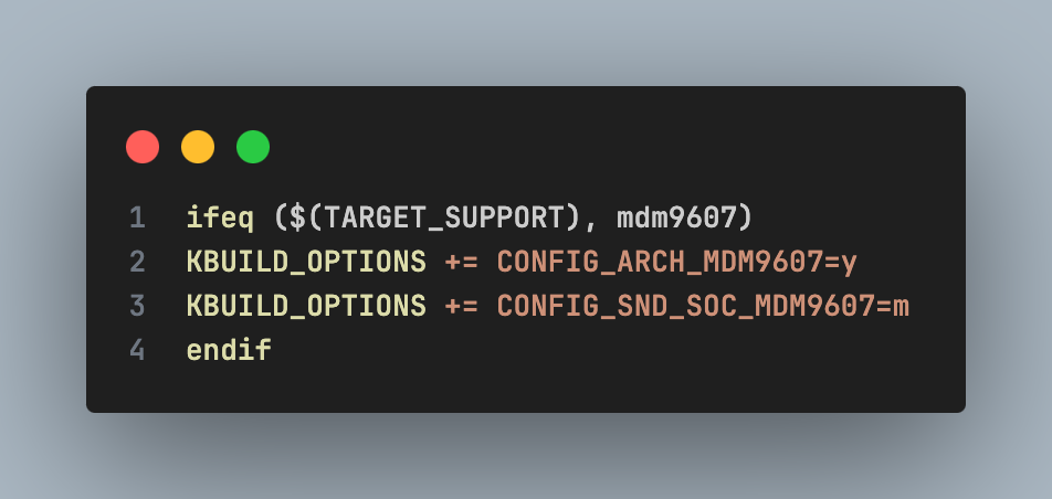
4.3. Add support Sound Card into Build System
Change Makefile To ensure mdm9607 is compiled correctly.
- File:
/apps_proc/vendor/qcom/opensource/audio-kernel/Makefile.am. Add to conditional block (Makefile):
- File:
/apps_proc/vendor/qcom/opensource/audio-kernel/Makefile:
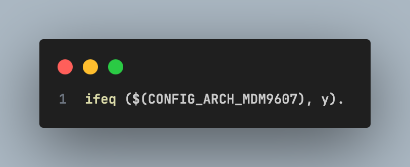
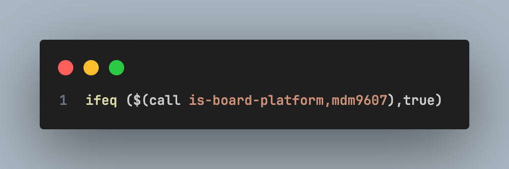
- Edit file /apps_proc/vendor/qcom/opensource/audio-kernel/asoc
5. Device Tree Integration for TLV320AIC3254
You need to declare a node for the TLV320AIC3254 codec on the I2C bus and configure the sound card to link the components.
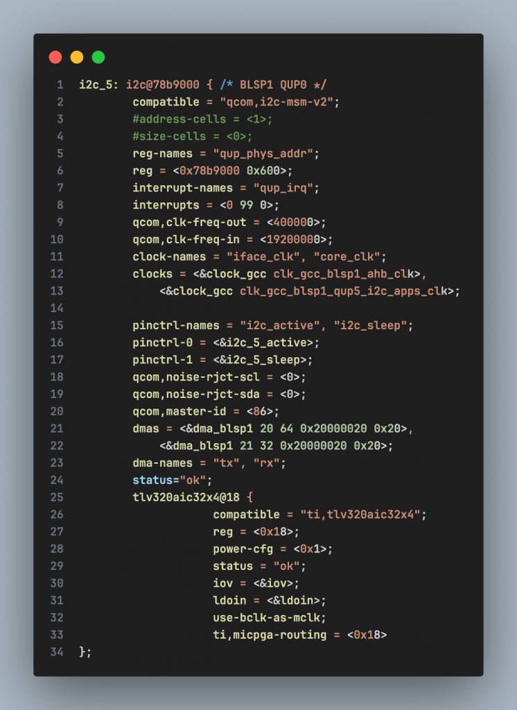
5.1. Declarate I2C Controller and Codec Node
Add node tlv320aic32x4 into node i2c_5 (BLSP1 QUP5).
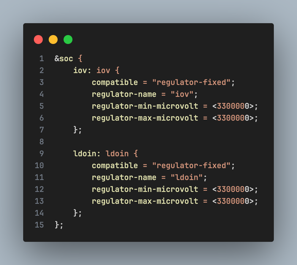
5.2. Declarate Regulator (Source)
Add virtual power nodes if the hardware does not use PMIC for direct control:
5.3. Declarate Sound Card (MDM9607 Audio Common)
Define the sound card to link the CPU DAI and the Codec DAI.
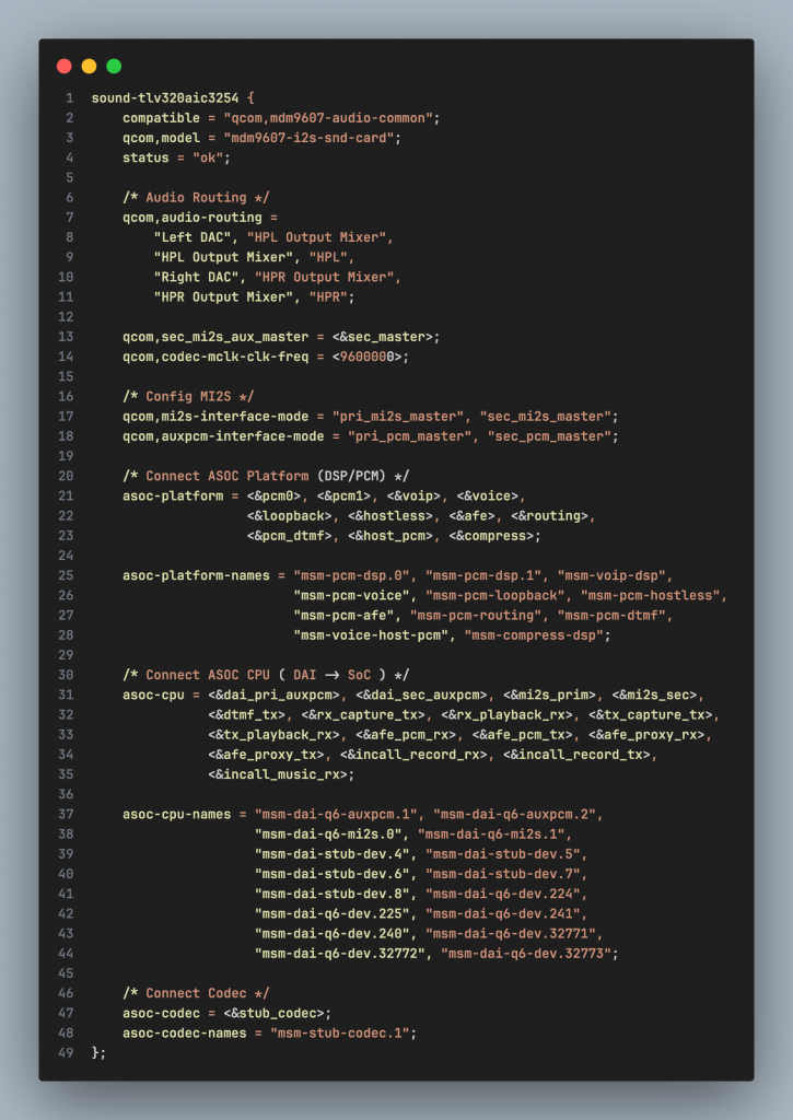
Note: You need to disable any other default sound cards (e.g., sound-9330, sound-9306) to avoid conflicts.
6. Verifying TLV320AIC3254 Driver Operation
6.1. Checking Sound Card Registration
Using cat /proc/asound/cards To confirm that the system has recognized the new sound card.
Result expected:
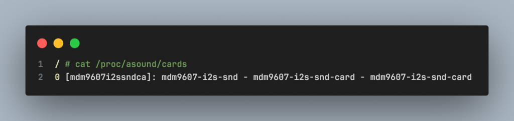
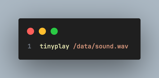
6.2. Testing Audio Playback Using WAV Files
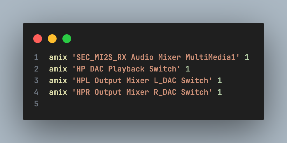
Configure the Mixer and play the music file to your headphones.
- Hardware connection: Plug your headphones into the J4 jack on the CC3200 codec board.
- Mixer configuration (Routing): Run the following commands to enable audio routing:
- To play music: Push the sound.wav file to the device and run the play command: