1. Introduction – CAN Protocol Overview
2. CAN Standard & ISO (11898-1, 11898-2, 11898-3)
3. Network Topology & Physical layer
4. CAN Frame Types
4.1. Data Frame
4.2. Remote Frame
4.3. Error Frame
4.4. Overload Frame
5. Message fields & Arbitration
6. Error detection & Bus fault handing
7. CAN FD Overview
8. Higher layer protocols on CAN
9. Application
9.1. CAN Bus (Classical CAN)
9.2. CAN FD (Flexible Data rate)
10. Conclusion
1. Introduction – CAN Protocol Overview
CAN (Control Area Network) is a highly reliable multipoint serial communication standard first developed by Robert Bosch GmbH, Germany, in 1986 when they were asked by Mercedes to develop a communication system between three ECUs (electronic control units) in a vehicle. Although UART (Universal asynchronous receiver-transmitter) is a widely used protocol, it does not adequately meet the requirements of multi-node systems, high-noise environments, and the demanding reliability requirements of the automotive industry. CAN was designed to address these limitations. The CAN bus operates effectively in high electromagnetic interference environments with twisted pair CAN High and CAN Low wires combined with fault checking and automatic fault detection mechanisms. Devices within the same bus are called nodes; a system can add several nodes, ranging from a few hundred to several kilometers, while still ensuring signal transmission. A key feature of CAN is its ID-based prioritization (arbitration) mechanism, which allows messages to be transmitted earlier without causing data conflicts. It offers high-speed transmission rates of up to 1 Mbits/second to enable time-based control.
Based on Bosch’s technical specifications, version 2.0 of CAN is divided into two parts:
- Standard CAN (Version 2.0A): uses an 11-bit ID (Identifier).
- Extended CAN (Version 2.0B): uses a 29-bit ID.
The two parts are defined by different message IDs, with the main difference being the length of the ID code. There are two ISO standards for CAN. The difference lies in the physical layer: ISO 11898 handles high-speed applications up to 1 Mbit/second, and ISO 11519 has an upper limit of 125 kbit/second; larger data sizes meet the needs of modern systems. Thanks to these advantages, CAN buses are widely used not only in automotive but also in industrial, medical, aerospace, and automation fields.
2. CAN Standards & ISO (11898-1, 11898-2, 11898-3)
OSI Layers
The OSI (Open Systems Interconnection) reference model, proposed by ISO, aims to standardize data communication processes in network systems. The OSI model comprises seven layers, each responsible for a distinct function, from physical signal transmission to application-level data processing, enabling different systems to communicate compatiblely and efficiently.
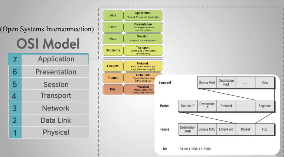
In practice, not all communication protocols fully implement all seven layers of the OSI model. For embedded systems and industrial control networks, especially in the automotive sector, protocol architectures are often simplified to reduce latency, increase reliability, and meet real-time requirements. A typical example is CAN Bus (Controller Area Network); a serial communication protocol designed for distributed control systems where multiple nodes need to exchange data with high reliability and fast response times. CAN does not fully implement all seven OSI layers, but mainly focuses on the two lowest layers:
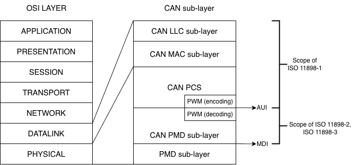
- Physical Layer: defines the transmission medium, voltage levels, connection methods, and signal characteristics.
- Data Link Layer: defines the transmission frame structure, bus access mechanism, error detection, and collision handling.
The remaining layers of the OSI model (Network, Transport, Application, etc.) are usually implemented through higher-layer protocols such as CANopen, J1939, or are defined by the manufacturer.
ISO 11898
To ensure the compatibility and stable operation of the CAN Bus in various environments, the CAN protocol has been standardized in the ISO 11898 standard. This standard details how CAN operates in relation to the layers of the OSI model, specifically:
- ISO 11898-1: Specifies the Data Link Layer and Physical Signalling mechanism of the CAN protocol, which serves as the core of the CAN Bus architecture. This standard details the structure of the CAN transmission frame, including Data Frame, Remote Frame, Error Frame, and Overload Frame, and defines the bus access mechanism through a contention process based on the priority level of the identifier (ID). In addition, ISO 11898-1 also specifies error detection and handling methods such as CRC, bit stuffing, ACK acknowledgment mechanism and error counters, as well as bit synchronization and data transmission timing techniques. This standard supports both standard CAN with 11-bit identifiers and extended CAN with 29-bit identifiers, ensuring reliable communication between nodes in a CAN network, avoiding data conflicts, and automatically detecting errors during transmission.
- ISO 11898-2 defines the Physical Layer for High-Speed CAN, commonly known as High-Speed CAN (HS-CAN), to meet the requirements of systems with high bandwidth and low latency. According to this standard, CAN can achieve transmission speeds up to 1 Mbps and uses differential twisted pair CAN_H and CAN_L to enhance noise immunity. The dominant and recessive states are distinguished by differential voltage levels, where CAN_H and CAN_L are approximately 3.5 V and 1.5 V respectively in the dominant state, and approximately 2.5 V in the recessive state. ISO 11898-2 requires the use of 120 Ω termination resistors at both ends of the bus to ensure signal quality, making this standard widely applied in critical control systems such as engine ECUs, ABS, ESP, and automotive drive and safety systems.
- ISO 11898-3: Describes the physical layer for low-speed, fault-tolerant CAN, also known as Low-Speed or Fault-Tolerant CAN, with the goal of maintaining system operation even in the event of a transmission failure. This standard supports a maximum transmission speed of 125 kbps and allows the CAN network to continue operating if one of the two transmission wires is broken. Unlike high-speed CAN, ISO 11898-3 does not require bus termination resistors and incorporates mechanisms for detecting and isolating faulty nodes to improve system reliability. Thanks to these characteristics, CAN according to ISO 11898-3 is often used in vehicle systems such as door, window, and light control, and applications that do not require high speed but need stability and safety in harsh working environments.
Thus, ISO 11898 serves as a bridge between the OSI model and the practical implementation of CAN Bus, helping to clearly define which layers CAN operates at and ensuring standardization in modern embedded systems and control networks.
3. Network Protocol & Physical layer
In a CAN Bus system, nodes are connected using a bus topology, where all devices share a common transmission line. Each node is connected in parallel to the bus via a pair of CAN_H and CAN_L wires, allowing multiple nodes to participate in communication without a central control device. This topology reduces the number of connecting wires, simplifies the system, and increases scalability. Bus access is controlled by non-destructive arbitration, ensuring that high-priority messages are transmitted first without losing data from other nodes.
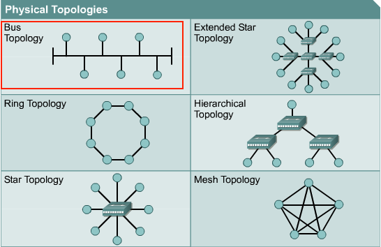
Bus Topology model
At the physical layer, the CAN Bus uses differential signaling via two lines, CAN_H and CAN_L, to enhance electromagnetic interference resistance. In the recessive state (logic ‘1’), the voltages on the CAN_H and CAN_L lines are approximately equal and usually around the common-mode voltage, around 2.5 V. When transmitting a dominant bit (logic ‘0’), the transmitter creates a voltage difference between the two lines, where CANH is pulled up to a higher voltage level and CAN_L is pulled down to a lower voltage level. The receiver does not rely on absolute voltage values but decodes data based on the differential voltage difference between CAN_H and CAN_L, helping the CAN system operate stably in high-noise environments such as automotive and industrial applications.
The figure below illustrates the principle of differential signal transmission and reception in the CAN Bus at the physical layer, showing the block structure of the CAN transmitter circuit, the CAN_H and CAN_L voltage waveforms corresponding to the dominant and recessive states on the bus, as well as the operating principle of the receiver circuit based on the differential voltage comparator. Through this mechanism, the CAN Bus ensures reliable information transmission while effectively supporting bus contention and error detection.
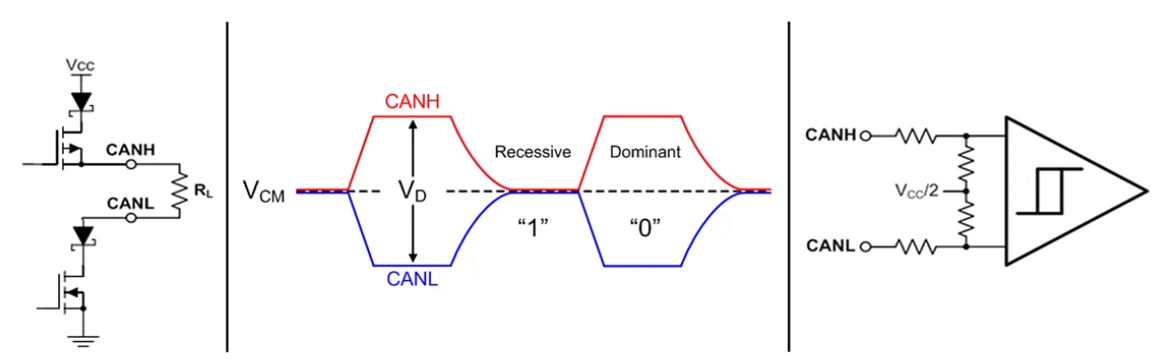
The principle of differential signal transmission and reception of the CAN Bus at the physical layer
Furthermore, to ensure signal quality during transmission, CAN Bus requires the use of termination resistors, typically 120 Ω, placed at both ends of the bus. These resistors reduce signal reflections and maintain stable transmission impedance. Bus length and transmission speed are inversely proportional; as transmission speed increases, the allowable bus length decreases. Thanks to the combination of a simple bus topology model and a physical layer using differential communication, CAN Bus achieves high reliability, good noise immunity, and is widely used in embedded systems, especially in the automotive field.
4. CAN Frame Types
4.1. Data Frame
frame data of can
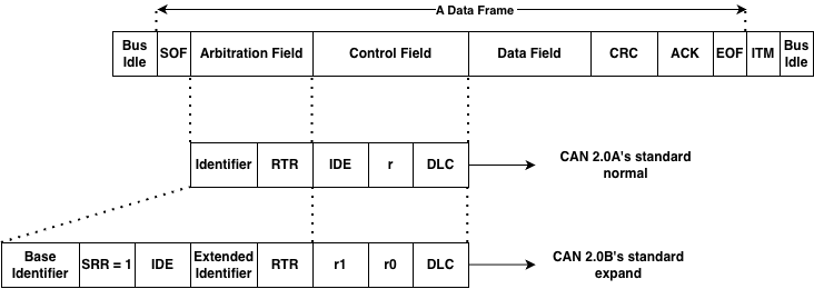
A CAN data frame is the basic communication unit on the CAN bus, used to exchange information between nodes in the system. A CAN frame begins and ends when the bus is idle, ensuring all nodes are ready for data transmission.
The data frame starts with the SOF (Start Of Frame) field, which includes a dominant bit used to synchronize all nodes on the bus and signal the start of a new data transmission session.
Next is the Arbitration Field, which determines the priority level of a message when multiple nodes are transmitting simultaneously. This field contains the Identifier (ID) and the RTR (Remote Transmission Request) bit. The illustration shows both CAN formats: standard with an 11-bit ID and extended with a 29-bit ID. In the arbitration mechanism, messages with smaller IDs have higher priority and are transmitted first without collisions.
Next is the Control Field, which includes bits identifying the frame type (IDE), reserve bits, and DLC (Data Length Code). The DLC indicates the number of bytes of data transmitted in the Data Field, up to 8 bytes for the CAN 2.0 standard.
The Data Field contains the actual information content of the message. Depending on the DLC value, this field can be from 0 to 8 bytes long. This is the main payload used by ECUs to exchange status, control commands, or sensor data.
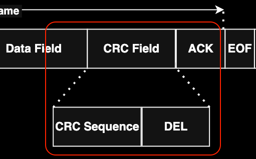
To ensure data integrity, the CAN frame includes a CRC Field, which contains the CRC error check code. The receiving node recalculates the CRC and compares it to the received CRC to detect errors during transmission.
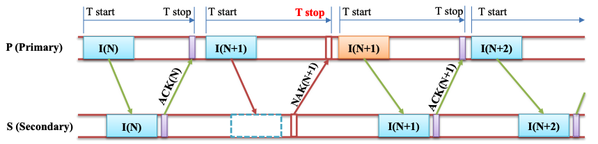
Next is the ACK Field. If a node receives valid data, it pulls the bus down to the dominant level to send an acknowledgment signal. Failure to receive an ACK will cause the transmitting node to automatically retransmit the message.
The data frame ends with EOF (End Of Frame), a 7-bit recessive, marking the end of the transmission. This is followed by Intermission, a short pause required before any new CAN frames can be sent.
4.2. Remote Frame
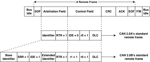
Besides Data Frames used for data transmission, Remote Frames are used to request data from any node on the same bus. However, remote frames are rarely used in automotive projects because data transmission is not request-based but primarily proactive, relying on information from the car’s specifications. Similar to Data Frames, the frame is clearly marked as a Remote Frame via the RTR bit, and this frame does not have a data field. Depending on the CAN network implementation, responses may be sent automatically. Simple CAN controllers (BasicCAN) cannot respond automatically. In this case, the Master microcontroller recognizes the remote request and must send data proactively.
4.3. Error Frame
Error Frames are distinctly different from CAN framing rules. They are transmitted when a node detects an error and will cause other nodes to detect the error as well, so they will also send this frame; the transmitter then automatically retransmits the message.
4.4. Overload Frame
Overload Frames are mentioned here for completeness only. They are very similar to Error Frames in format and are transmitted by a node when that node is too busy. Overload Frames are not used frequently, as modern CAN controllers are smart enough not to use them. In fact, the only controller that would generate an Overload Frame is the now-obsolete 82526.
5. Message fields & Arbitration
In the CAN Bus protocol, data is transmitted as message frames (CAN messages), where each message carries both application data and bus access priority. Unlike node-addressed protocols, CAN uses message-based communication, meaning the message content is determined by an identifier (ID), and any node on the bus can receive the message if that ID matches its configuration.
The arbitration mechanism (bus contention) is a key feature of the CAN Bus, allowing multiple nodes to start transmitting at the same time without data loss. Arbitration takes place in the Identifier field of the CAN frame and is based on the principle of bit-wise non-destructive arbitration. During transmission, each node both transmits its data and monitors the actual state of the bus. Due to the physical characteristics of the CAN Bus, the dominant bit (logic ‘0’) always overwrites the recessive bit (logic ‘1’). When a node transmits a recessive bit but reads a dominant bit on the bus, that node immediately recognizes that it has lost bus access and will stop transmitting, entering a waiting state to try again when the bus is free.
The diagram illustrates the arbitration process when multiple CAN nodes simultaneously transmit messages. At the beginning bits of the Identifier field, the nodes transmit the same value, so the arbitration process continues. When a difference appears at a certain bit position, the node transmitting the recessive bit will be excluded from the dispute, while the node transmitting the dominant bit will continue transmitting. As a result, the message with the smaller binary Identifier will gain bus access and be transmitted completely first.
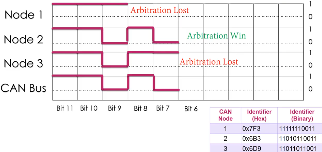
Illustrating the CAN Bus arbitrage mechanism based on the Identifier field
Thanks to this non-destructive arbitration mechanism, CAN Bus ensures that high-priority messages are always transmitted first without data retransmission, while maintaining the reliability and determinism of the system. This is why CAN Bus is widely used in real-time systems such as automotive control networks and industrial automation, where ensuring the order and latency of communication is crucial.
6. Error detection & Bus fault handing
Bit Error
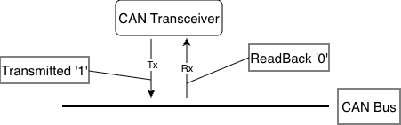
bit error by transmitted
In the CAN protocol, every time a node transmits a bit onto the bus, it simultaneously “reads back” the bus’s state at that moment. In principle, if the transmitted value (TX) differs from the received value (RX), a Bit Error is detected. In the diagram above, the node is sending bit 1 but reading bit 0, which triggers a bit error. Bit errors can occur due to several reasons:
- Arbitration Process: This is the normal scenario; if two nodes transmit simultaneously, the node transmitting bit 0 (higher priority) will prevail over the node transmitting bit 1. When the node transmitting bit 1 sees a 0 on the bus, it understands it has “lost” the priority claim and stops transmitting to yield the right of way.
- Physical Fault: If this occurs in the data field or areas not eligible for adjudication, it could be due to: the CAN line is short-circuited to ground or power, excessive electromagnetic interference (EMI) causes voltage levels to fluctuate across the bus, the transceiver is broken.
When this error is detected (except during the arbitration phase), the node detecting the error will immediately send an Error Flag to notify all other nodes on the network that the current data is no longer trustworthy and needs to be retransmitted.
Stuff Error (Stuffing Error)
stuff error by receiver
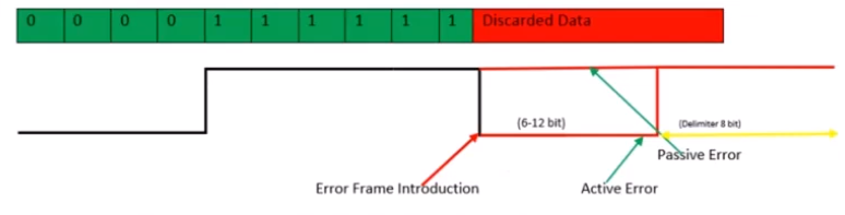
To ensure that receivers can maintain synchronization with transmitters, the CAN protocol uses Bit Stuffing: This rule states that after every 5 consecutive bits with the same logic level (all 0 or all 1), the transmitter automatically inserts a reverse-biased bit to create “edges” (voltage level transitions) so that other nodes can readjust their internal clocks, avoiding clock misalignment when encountering a long, constant data stream.
This error occurs when a receiving node detects 6 consecutive bits with the same logic level on the bus (in areas where bit stuffing rules are applied, such as SOF to CRC). In your image, the bit sequence is 00000 (5 bits of 0), then instead of a stuff bit of 1, the bus displays consecutive 1 bits or other errors that violate the rule. When there are 6 bits of the same level (like the red “Discarded Data” segment), the receiving node identifies this as a Stuffing Error.
When a Stuffing Error is detected, the node will send an Error Frame to discard the current message: Error Frame Introduction: The moment the node detects the error and begins inserting error flags onto the bus.
- Active Error (6-12 bits): If the node is in the “Error Active” state, it will send 6 consecutive Dominant bits (level 0). Because other nodes will also see this 6-bit sequence as violating the Bit Stuffing rule, they will also send their own Error Flag, creating a sequence of 6 to 12 bits on the bus.
- Passive Error: If the node is in the “Error Passive” state (has encountered many errors before), it will send 6 Recessive bits (level 1). This does not interrupt the bus if other nodes are still operating normally. Delimiter (8 bits): After sending the error flag, the node will send an 8-bit Recessive (level 1) to signal the end of the error frame and prepare for retransmission.
As soon as an Error Frame appears, all previous data in the frame (Data Frame) is considered invalid and discarded by the receiving nodes. The transmitting node will have to retransmit the entire message from the beginning after the connection is stable again.
CRC Error
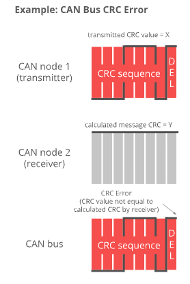
CAN Node 1 (Transmitter): The node that sends the message. It calculates a value based on the data content and sends it as a CRC Sequence (the transmitted value is X). CAN Node 2 (Receiver): The node that receives the message. Upon receiving the data, it performs a similar mathematical calculation on the received bits to produce the result Y (Calculated message CRC = Y). CAN Bus: The physical transmission medium where the CRC signal is transmitted.
CRC errors are detected at the receiver when the data is altered during transmission: If there is no interference, the value X (sent) should equal the value Y (recalculated). However, if one or more data bits are altered due to electromagnetic interference, the calculated value Y will differ from X. The image caption reads: “CRC Error (CRC value not equal to calculated CRC by receiver)”. This means that when X differs from Y, the receiving node identifies this as a CRC error. One key difference between CRC errors and other errors is the timing of their detection and processing:
- DEL (Delimiter) area: CRC errors are only checked after the entire CRC string has been received, specifically at the CRC Delimiter (CRC separator bit) location.
- Response: Immediately after the DEL bit, if the node detects an error, it will not send an ACK (Acknowledge) bit but instead will send an Error Frame to request the transmitting node to resend the data.
Acknowledgment Error (ACK Error)
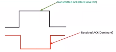
Unlike other communication protocols, in a CAN network, the receiver is responsible for confirming receipt of the data in the correct format. The transmitter sends a Recessive bit (level 1) at the ACK slot. Then, at the receiver, all nodes that receive the correct message (passing the CRC check) simultaneously pull their bus down to the Dominant level (level 0) at that moment to confirm receipt.
The diagram illustrates the contrast between the transmitted and received signals on the bus:
- Transmitted Ack (Recessive Bit): This is the signal from the transmitting node. It lets the bus go loose (level 1) and “listens” to see if any node acknowledges the connection.
- Received ACK (Dominant): This is the actual state on the CAN Bus. When at least one other node receives the data, it overwrites the bus with a 0.
- Normal result: The transmitting node reads back and sees level 0 (Dominant) even though I sent level 1 → Communication successful.
An ACK Error is acknowledged by the transmitting node when the transmitting node sends a Recessive (1) bit in the ACK slot but upon rereading the bus it is still at the Recessive (1) level, which means that no node on the network acknowledges receipt of that message.
Form Error
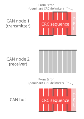
An error occurs when the structural components within a CAN data frame are misaligned at the logical level. In the CAN protocol, there are certain positions that must be Recessive bits (level 1) to mark the separation of message parts. A Form Error occurs when a receiving node detects a Dominant bit (level 0) at one of these fixed positions.
In your image, the specific error is indicated as:
Dominant CRC Delimiter: By standard, the DEL (Delimiter) bit immediately following the CRC sequence should always be a 1 (Recessive).
Phenomena: Both CAN node 1 (transmitter) and the CAN bus are displaying a 0 (Dominant) bit at this DEL position. Therefore, the system identifies this as a formatting error.
In addition to the CRC Delimiter position shown in the image, formatting errors can also occur at:
- ACK Delimiter: The delimiter bit after the acknowledgment slot (ACK Slot).
- End of Frame (EOF): A 7-bit Recessive sequence that ends a frame.
Similar to other errors, when a node detects a Form Error: It will transmit an Error Frame starting from the next bit.
The message being transmitted will be discarded: The transmitting node will increment the error counter and prepare to retransmit the message.
Bus Fault Handling
When an error is detected on the CAN bus, the system reacts immediately to protect data integrity and maintain network stability. CAN supports automatic error detection and a hierarchical fault-handling mechanism, enabling nodes to quickly detect anomalies and prevent faulty frames from propagating on the bus.
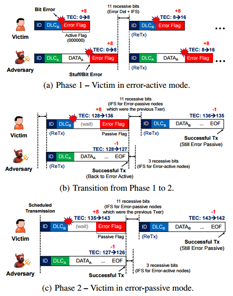
As illustrated in the figure, when a bit error or stuff error occurs, a node in the error-active state transmits an Active Error Flag, which interrupts the current frame and forces a retransmission. At the same time, the node’s Transmit Error Counter (TEC) is incremented, reflecting the severity of the error.
If the accumulated error count exceeds the predefined threshold, the node transitions to the error-passive state. In this state, the node transmits only a Passive Error Flag (recessive bits), reducing its impact on the bus while still allowing it to participate in communication. If subsequent transmissions are successful, the TEC gradually decreases, enabling the node to recover and return to the error-active state.
This mechanism demonstrates that CAN not only detects transmission errors but also automatically isolates and recovers faulty nodes, ensuring that correctly operating nodes can maintain stable communication. As a result, CAN achieves high reliability and is particularly suitable for safety-critical and real-time systems.
7. CAN FD Overview
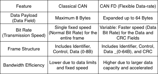
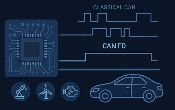
CAN is short for ‘Controller Area Network’, and CAN FD is short for CAN with Flexible Data rate. Controller area network is an electronic communication bus defined by the ISO 11898 standards. In 2015 these standards were updated to include CAN FD as an addition to the previous revision, and the new reference number ISO 11898-1:2015(E) was assigned. The standard is written to make the information unambiguous, which unfortunately makes it hard to read because there are no extended descriptions or examples. The information in this tutorial is less formal, and designed to be easier to understand.
Collectively, this system is referred to as a CAN network, with Classical CAN and CAN FD as different Frame Formats supported by the standard.
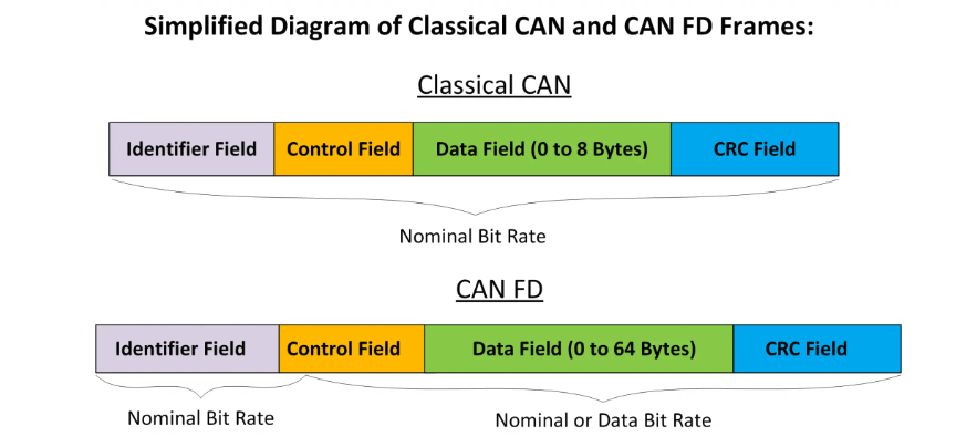
This diagram provides a visual comparison between two data transmission framework standards in control networks: Classical CAN and CAN FD. Below is a detailed description of the components:
8. Higher layer protocols on CAN
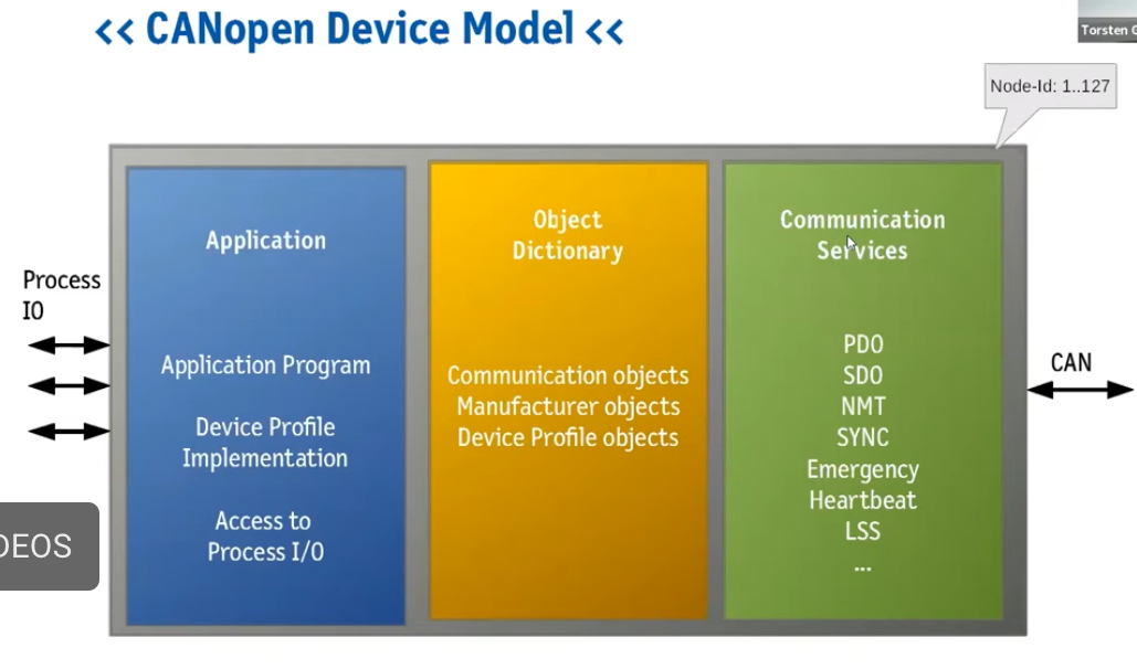
figure 1: data processing
The CANOpen device model is a standardized architecture that enables embedded devices to communicate uniformly within an industrial network. This architecture comprises three core components:
- The Application Layer: This is where application programs run and device profiles are executed to process data directly from physical input/output ports (Process I/O).
- The Object Dictionary: This acts as the central data management hub, storing communication objects, manufacturer objects, and device specifications.
Communication Services: This area is responsible for encapsulating and transmitting data over the CAN network using specific protocols such as PDO for real-time data transmission, SDO for configuration, and network management services like NMT, Heartbeat, and SYNC.
The entire model allows for the management of up to 127 nodes (Node-IDs) on the same network, creating high flexibility and compatibility between devices from various manufacturers.
In complex network control systems, the combination of device model and identification structure plays a crucial role in the stable operation of the entire system. Specifically, the CANopen device model provides a logical framework comprising the Application layer, Object Dictionary, and Communication Services to standardize how a device processes data. However, for these devices to accurately “identify” each other on the network without conflicts, the system needs an electronic “identity card” such as the NAME Field identification structure (according to the J1939/ISOBUS standard).
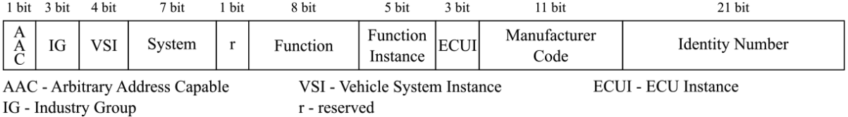
figure 2: identity verfication
Through this 64-bit string, information from the application layer such as device function, manufacturer code, and unique identifier number is tightly encapsulated. This connection allows communication services in the CANopen model to use detailed identifiers to perform automatic address claiming, making it easy for devices to integrate and communicate in real time as soon as they connect to the system.
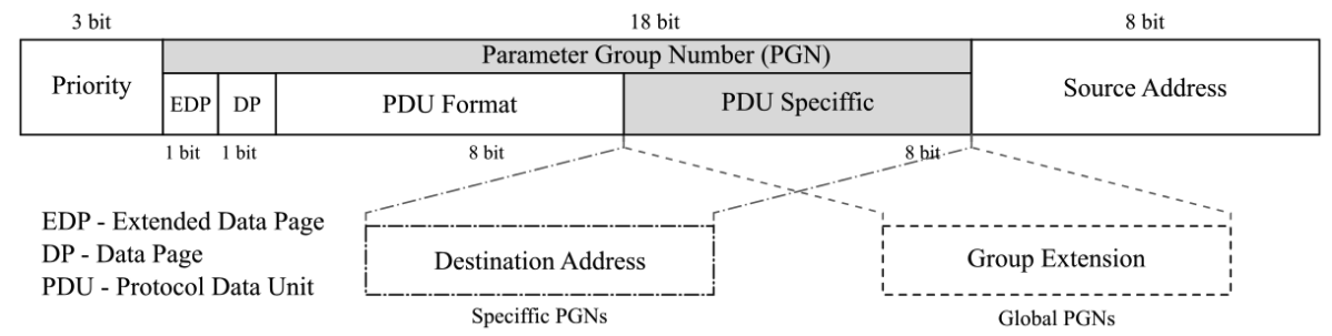
figure 3: the information to its correct destination
The CAN network communication system is a close coordination between device architecture, identity, and communication method:
First, the CANopen device model establishes the internal logic foundation, where data from the Application layer is managed in the Object Dictionary and ready to be transmitted through Communication Services. For a device to join the network, it needs a unique “identity” – a 64-bit NAME field. This structure contains information such as the Manufacturer Code and Function, allowing the device to automatically establish its identity and obtain a unique Source Address without conflict.
Finally, when the actual data is sent, the 29-bit Identity Framework directly coordinates the information on the transmission path. Here, the established source address is combined with the Priority and the number of Parameter Groups (PGNs) to precisely define the data type and destination. This linkage creates a complete cycle: from data processing at the device (Figure 1), identity verification (Figure 2), to shipping labeling to deliver the information to its correct destination (Figure 3).
9. Applications
9.1. CAN Bus (Classical CAN)
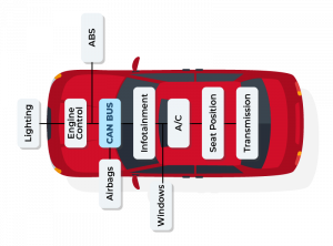
- CAN Bus (Classical CAN) – Automotive: CAN buses are widely used in automobiles to transmit data between ECUs such as the engine, ABS, airbags, transmission, and instrument cluster. For example, data from the Engine Control Unit can be transmitted to the Transmission, ABS, and Dashboard to control and monitor vehicle operation. The biggest benefit is reducing the number of wires in the vehicle and ensuring reliability through bus arbitration and error detection.
- CAN Bus – Industrial Automation: In industrial automation, CAN connects PLCs, sensors, and actuators. Typical applications include industrial robots, conveyors, and CNC machines. For managing more complex data, higher-layer protocols such as CANopen and DeviceNet are used, making device synchronization and management easier.
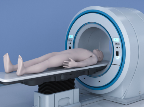
- CAN Bus – Medical Devices: Medical devices such as diagnostic imaging machines or patient monitors use CAN to transmit real-time data. CAN ensures accurate data with low latency, meeting stringent safety and reliability requirements.
- CAN Bus – Maritime & Aviation: In ships and UAVs, CAN is used to monitor and control engine, radar, and GPS systems. It provides stable communication, is resistant to electromagnetic interference, and is suitable for industrial or maritime environments.
- CAN Bus – Building Automation: CAN is also applied in smart building control, such as HVAC, lighting, and security systems. Thanks to its stable and robust communication capabilities, CAN helps reduce signal errors and increase reliability for automation systems.
9.2. CAN FD (Flexible Data rate)
- CAN FD – Automotive & High Data Applications: CAN FD (Flexible Data Rate) is an upgraded version of CAN, supporting larger frames (64 bytes) and higher transmission speeds. In modern automobiles, CAN FD is used to transmit data from cameras, radar, lidar, and infotainment systems. For example, ADAS (Advanced Driver Assistance Systems) systems use CAN FD to ensure real-time data, reduce the number of frames to be transmitted, and increase processing speed.
- CAN FD – Industrial Automation & High Throughput: In industry, CAN FD helps transmit multiple sensor and actuator data in a single frame, reducing latency and increasing system response speed. This is crucial for industrial robots, CNC machines, or devices requiring real-time data.
- CAN FD – ADAS & Autonomous Vehicles: CAN FD is the optimal choice for autonomous vehicles and advanced driver assistance systems where data from cameras, radar, and lidar needs to be transmitted continuously at high volumes. The large frame size and high speed of CAN FD ensure that data is processed promptly and accurately.
- CAN FD – Medical & Electric/Hybrid Vehicles: CAN FD is also used in MRI, CT, or multi-sensor monitoring devices where large amounts of image or data need to be transmitted quickly. In electric or hybrid vehicles, CAN FD helps manage the battery (Battery Management System) and sensors, transmitting battery status, temperature, and current data safely and at high speed.
10. Conclusion
CAN (Controller Area Network) is widely used because it provides reliable, fast, and cost-effective data communication. With its arbitration and error detection mechanisms, CAN ensures that critical data in embedded systems or vehicles is transmitted accurately and consistently, even in noisy environments.
One major advantage of CAN is its scalability and multi-node capability, allowing many devices to communicate on a single bus without excessive wiring, reducing cost and system complexity. Furthermore, with higher layer protocols such as CANopen, J1939, or DeviceNet, CAN not only transmits data but also supports device management, synchronization, and advanced fault handling, making it suitable for automotive, industrial, medical, and automation applications.
The advanced CAN FD provides larger data frames and higher data rates, meeting the demands of modern applications such as ADAS, electric/hybrid vehicles, industrial robots, and medical imaging systems. In summary, CAN is an ideal choice for any embedded system that requires high reliability, speed, and scalability.