1. Introduction
1.1. Introduce about nRF52840
1.2. Analog microphone vs PDM microphone
2. Mono and Stereo hardware
2.1. Mono mode
2.2. Stereo mode
3. Data processing stream
4. Conclusion
1. Introduction

1.1 Introduce about nRF52840
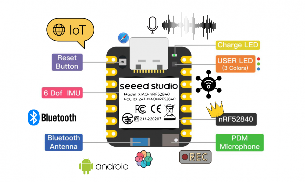
Seeed Studio XIAO nRF52840 is the first wireless board in the XIAO series, featuring the Nordic nRF52840 SoC with Bluetooth Low Energy 5.0 support. Its ultra-compact form factor, single-sided SMD design, and integrated Bluetooth antenna make it well-suited for mobile devices and rapid IoT prototyping.
The XIAO nRF52840 Sense variant integrates a digital PDM microphone and a 6-axis IMU, enabling real-time audio capture and motion sensing. These onboard sensors make it ideal for TinyML applications such as voice recognition, acoustic event detection, and gesture recognition. The upgraded XIAO nRF52840 Plus and Sense Plus versions further enhance usability by increasing the number of multifunctional pins to 20, adding I2S and SPI resources, exposing NFC pins, and optimizing the BAT pin placement for easier soldering and power integration. The board provides rich interfaces including UART, I2C, and SPI, with 11 digital (PWM) pins and 6 analog (ADC) pins, along with 2 MB of onboard flash memory. It supports multiple development environments such as Arduino, MicroPython, CircuitPython, and Zephyr SDK.
Typical Applications:
- Bluetooth Low Energy (BLE): low-power IoT devices, beacons, wearables, sensor data streaming
- Voice & Audio Processing: audio capture, voice recognition, keyword spotting
- Recorder: local audio recording or BLE audio transmission
- TinyML: gesture recognition, audio classification, edge AI
1.2. Analog microphone vs PDM microphone
In the nRF52840, both analog microphones and PDM (Pulse Density Modulation) microphones can be used. However, PDM microphones are generally preferred for high-quality digital audio applications such as audio-based machine learning. While analog microphones require an external ADC for signal digitization, PDM microphones output digital data directly. This allows tighter integration with the MCU, higher overall performance, improved noise immunity, and reduced GPIO usage—especially when using advanced PDM drivers provided by mbed OS or the Nordic SDK.
For analog microphones, to better understand their operating principle, we consider a typical circuit based on an electret microphone with a simple yet effective signal amplification structure. The electret microphone is powered through a bias resistor Rbias (typically in the range of 2.2 kΩ to 10 kΩ) connected from VDD to the signal pin. This biasing provides the correct operating conditions for the internal FET transistor inside the microphone.
The microphone produces an AC audio signal, which is separated from the DC component by a coupling capacitor C₁ before being fed into the op-amp input. At this stage, resistor R₁ sets the input impedance and, together with the op-amp, forms an amplification stage. Meanwhile, the VDD supply is stabilized using a bypass capacitor to reduce power-supply noise and prevent it from affecting the output signal.
With this configuration, the audio signal captured from the microphone is amplified in a stable manner, exhibits reduced noise, and achieves sufficient quality for further processing or digitization in subsequent stages. The overall circuit can be modeled as follows:
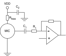
Diagram Analog microphone
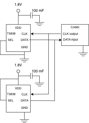
For PDM microphones, the operation follows the principle of digital pulse density modulation. The PDM microphone is powered via the VDD pin and connected to ground at the GND pin. Once the acoustic signal is captured, it is directly converted into a PDM bitstream inside the microphone and transmitted to the host circuit through the Data pin. The microphone’s operation and data synchronization are controlled by a Clock signal provided by the host and applied to the Clock pin of the microphone. In addition, the SEL (Select) pin—typically connected to the host circuit—allows selection between the Left or Right channel when multiple microphones share the same PDM bus. If only a single microphone is used, this pin can be fixed to a defined logic level by pulling it up or down through an appropriate resistor. To ensure signal stability and minimize noise, a bypass capacitor is usually placed close to the microphone’s VDD pin to filter power-supply noise. With this configuration, the system achieves stable digital audio capture, where data is streamed directly into the processing block without requiring an intermediate analog amplification stage. The overall structure can be summarized by the following block diagram:
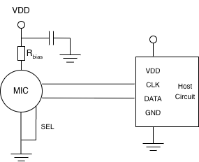
Diagram PDM microphone
The choice of using MEMS microphones with analog or digital output signals often depends on how the output signal will be used. Analog output signals are convenient if they are connected to an amplifier input for analog processing in the host system. Examples of common analog applications are simple loudspeakers or radio communication systems. MEMS microphones with analog outputs also tend to consume less power than microphones with digital outputs due to the absence of an ADC converter.
2. Mono and Stereo hardware
Based on the operating principle of PDM microphones, the audio signal is already digitized inside the microphone and streamed directly to the microcontroller via the PDM interface. This significantly simplifies the analog front-end and enables flexible microphone configurations. On the nRF52840 platform, the dedicated PDM hardware peripheral supports both mono and stereo microphone setups, making it suitable for a wide range of applications such as voice recognition, audio recording, and spatial audio processing. The following section describes in detail the hardware configurations for mono and stereo PDM microphones.
Mono mode vs Stereo mode
2.1. Mono mode
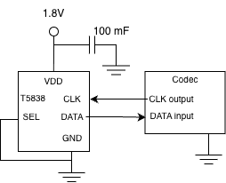
Connect Mono with Codec
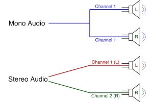
Mono (Monophonic) is an audio effect where sound is captured and played from a single source. Because it comes from a single source, it can be difficult to distinguish the location of the sound in space.
Fieldy firmware supports mono mode via both software and hardware:
- For hardware: Fieldy uses only one PDM microphone; the SEL pin of the microphone is fixed because it only uses one channel, and the MCY only reads one DATA stream.
- The microphone connects directly to the nRF52840’s PDM peripheral; it does not use an ADC or an external audio codec for recording.
Configuration of samples rate suitable voice:
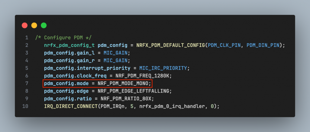
Configuration of PDM in Mono mode
In the driver microphone (mic.c):

mic.c settings
Calculate from here frequency for mono PCM is 16 KHz The suffer PCM 1 channel:
Besides, supporting mono mode in codec:
Opus encoder mono
No parameter for channel, PCM default is mono:
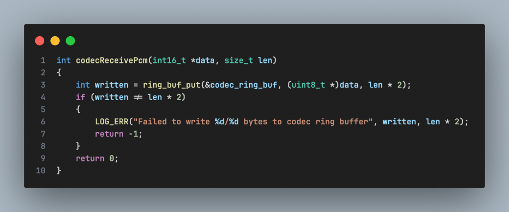
Codec API support only mono mode
Next, Fieldy firmware supporting in configuration the systems in this file config:
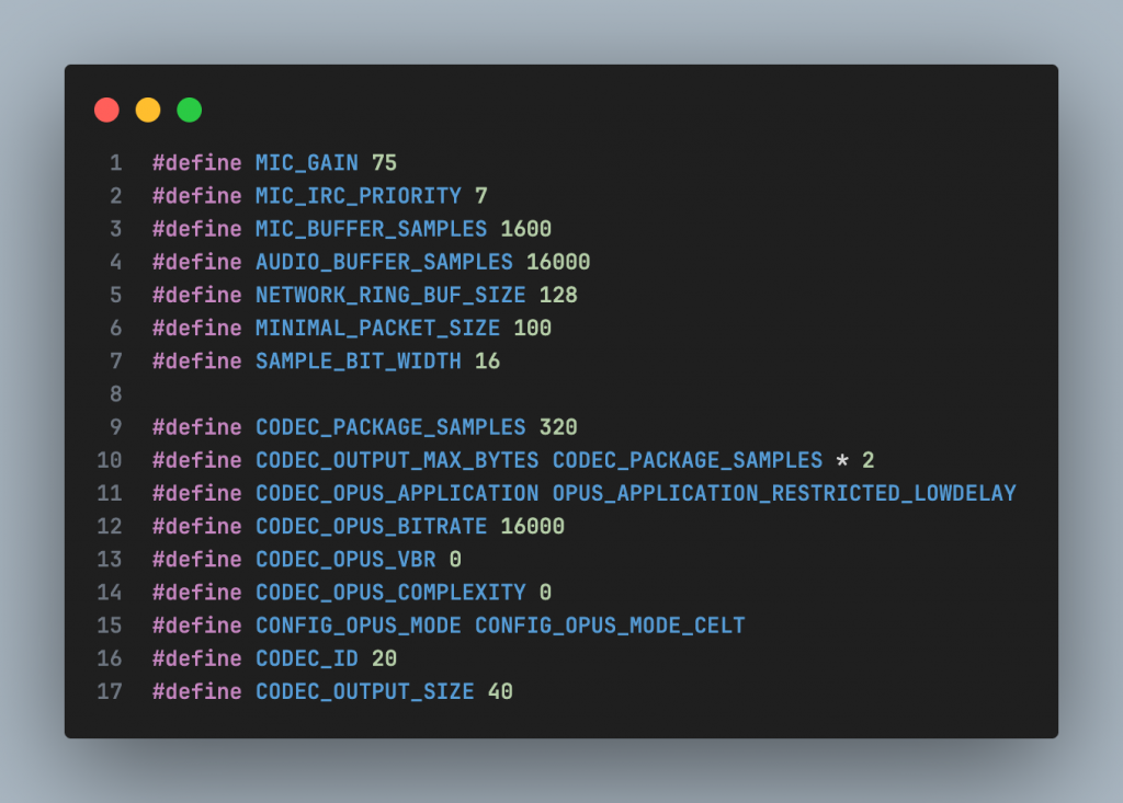
Configuration audio system
The audio system is configured for single-channel (mono) voice capture and encoding with a sampling frequency of 16 kHz. 16-bit PCM data is packed into 20 ms frames and compressed using the Opus codec in CELT mode, with a fixed bitrate of 16 kbps, to optimize low latency, low power consumption, and suitability for data transmission over BLE.
2.2. Stereo mode
Stereo sound is audio that is reproduced from two separate sound channels, played through a speaker system with a two-speaker configuration, or through headphones, allowing the listener to perceive the spatial position of sounds. Stereo sound is associated with spatial positioning through the variation of sound between the two component speakers, helping to distinguish left/right sound positions effectively.
Stereo mode
The nRF52840 MCU supports stereo audio recording via the PDM peripheral. However, in 6 the current Fieldy hardware design, only one PDM microphone is used and it is configured in mono mode. To implement stereo mode, a second microphone needs to be added or a stereo PDM microphone used (with integrated …), and the PDM peripheral and Opus codec must be reconfigured for two-channel operation.
3. Data processing stream
Data stream in single channel mode maybe set a diagram like:

Diagram of structure firmware
- PDM MIC: encode analog signals (Raw audio signals have frequencies 1-3MHz) into digital signal. nRF52840 PDM HW: PDM hardware in MCU; receive DATA, eliminate interference CIC, decrease frequency (decimation), finally export file .pcm.
- Before reaching the buffer, the signal is pulse-code modulated (converting the audio signal into a digital signal).
- Audio Buffer/DMA: The buffer help to improve the output signal, increase quality, decrease interference and output impedance,…
- Opus Encoder: Audio signal is compressed down to low bitrate, keep the quality of voice.
- BLE/Storage/RF: Finally, the signal is taken to perform the system’s required operations such
as transmission, storage, amplification, etc.
4. Conclusion
The nRF52840 is a capable and energy-efficient microcontroller platform for low-power audio applications. By leveraging PDM microphones and software-based audio processing, the system can operate reliably with a current consumption of approximately 2–3 mA at 3.8 V, making it well suited for battery-powered devices such as wearables, IoT nodes, and portable audio recorders.
However, due to the lack of a hardware audio codec, all audio encoding and decoding tasks (e.g., Opus) must be handled in software by the CPU. This results in lower processing efficiency compared to systems equipped with dedicated hardware codecs. Furthermore, the absence of a dedicated DSP unit means that digital signal processing tasks such as filtering, compression, and encoding consume additional CPU cycles, RAM, and power.
Overall, the nRF52840 is well suited for low-complexity to moderate audio workloads where power efficiency and flexibility are prioritized. For applications requiring high-performance, real-time audio processing, SoCs with integrated DSPs or hardware audio codecs may offer more optimal solutions.