1. Introduction
2. Flashing code
2.1. Generate HEX file for flashing
2.2. Flashing with SEGGER J-Flash Lite
3. Debugging
3.1. Debugging with e2 Studio Debugger
3.2. Debugging with Logs using J-Link RTT Viewer
4. Conclusion
1. Introduction
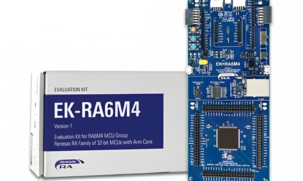
Welcome to this second part, where we will dive into the essential steps of flashing, debugging, and logging for the Renesas RA6M4 board. In the previous part, we covered the installation of necessary software and the process of project creation and building. Now, we will explore how to effectively flash your code onto the board, as well as invaluable techniques for debugging and logging. By mastering these steps, you can optimize your development process and ensure the smooth execution of your Renesas RA6M4 projects.
2. Flashing code
2.1. Generating a HEX file for flashing
Before flashing code to the RA6M4 board, it is necessary to obtain the output HEX file of the project. Follow these steps to generate the HEX file for flashing onto the board:
- In e² studio, double-click to select your BlinkLED project, then right-click and choose Properties
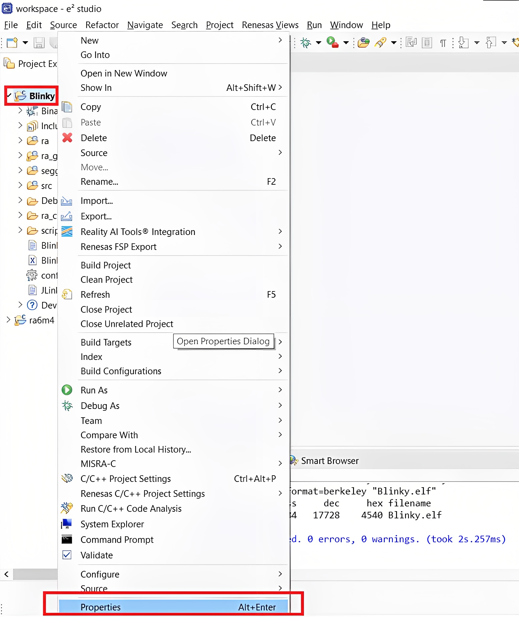
Opening project properties
- In the Project Properties dialog box, navigate to the C/C++ Build category. Click on the Settings tab. In the Tool Settings tab, expand the GNU ARM Cross Create Flash Image section. Select the General subcategory. In the Output format field, choose the desired output format, such as Intel Hex
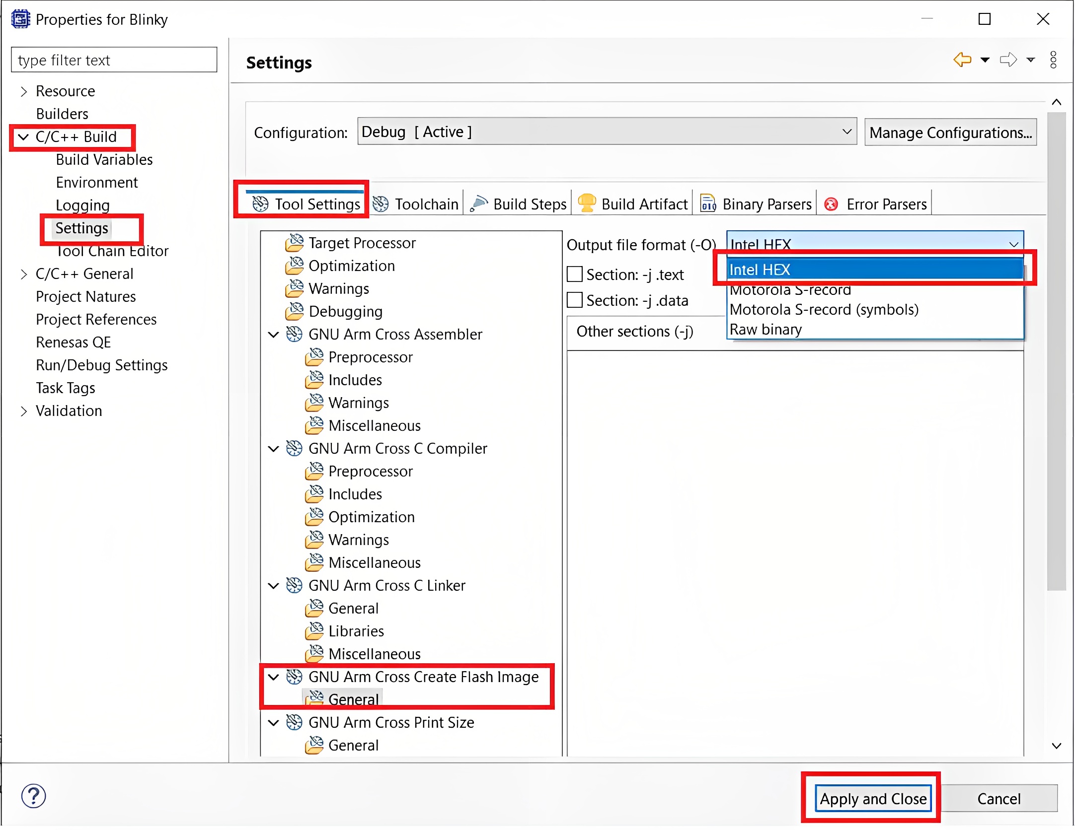
Changing the output file format
- Click Apply and then OK to save the changes.
- Now, rebuild your project, and you will find the hex output file in the {project_name}/Debug/ folder
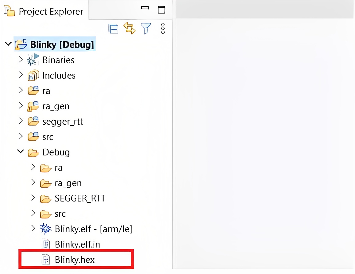
Finding the hex output file
2.2. Flashing with SEGGER J-Flash Lite
For code flashing purposes, we utilize SEGGER J-Flash Lite software. You can download and install J-Link Software Package by accessing the provided Download Link.

Downloading J-Link Software Package
- To program the Blink LED project onto the Renesas EK-RA6M4 board, it is essential to establish a debug connection between the Renesas EK-RA6M4 board and the host PC.
Note: The EK-RA6M4 board supports 3 debugging modes. In this section and the following sections, the default debugging mode, Debug On-Board, is used.
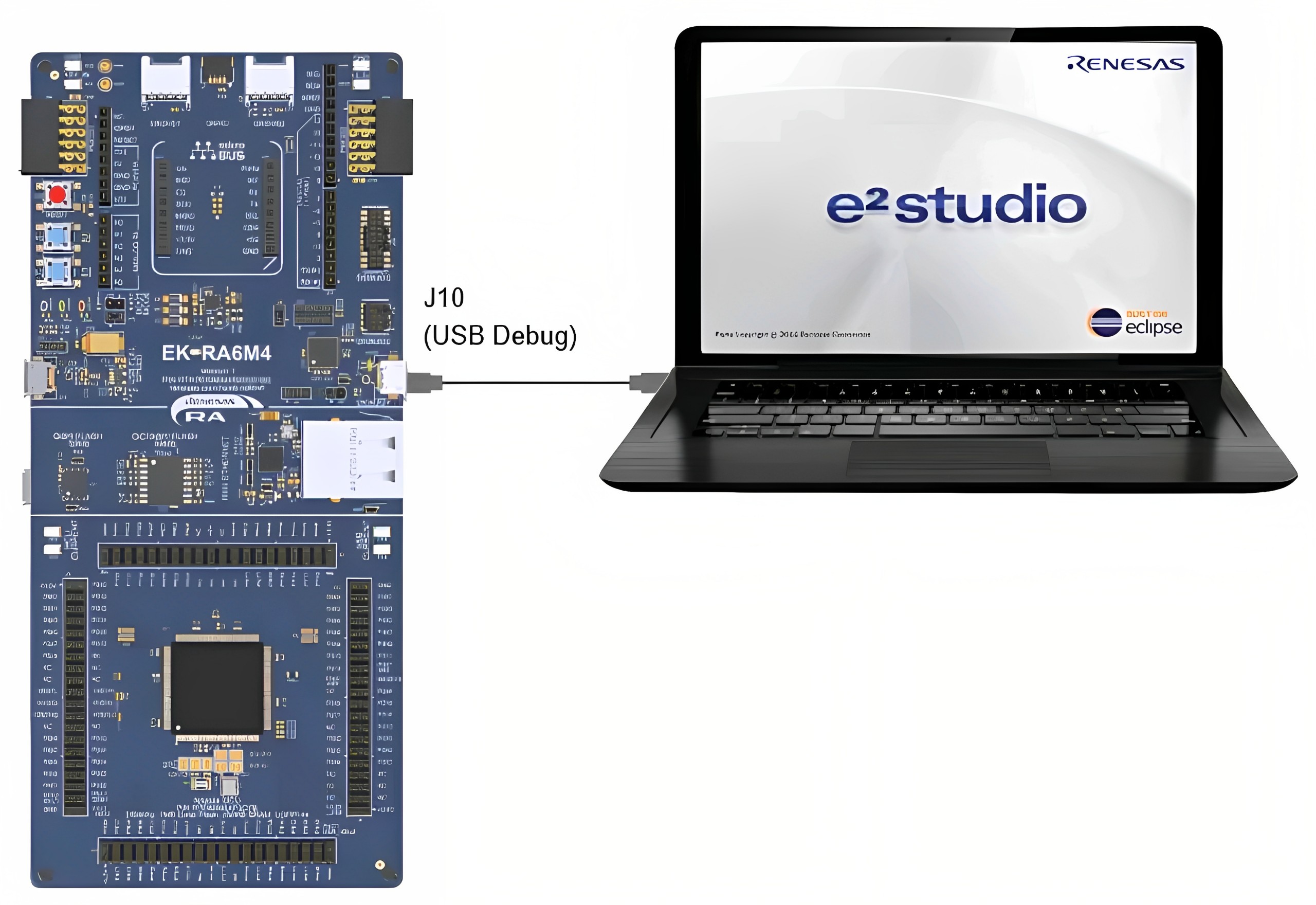
Connecting the Renesas EK-RA6M4 Board to the Host PC via USB Debug Port
- Verify that the debug LED (LED5) stops blinking and lights up orange indicating that the J-Link drivers are detected by the EK-RA6M4 board.
Note: The debug LED (LED5) continues to blink when J-Link drivers are not detected by the Renesas EK-RA6M4 board. In that case, make sure that the EK-RA6M4 board is connected to the host PC through the micro-B USB debug port (J10) and that J-Link drivers are installed on the host PC by checking in the Windows Device Manager (expand Universal Serial Bus controller, and locate J-Link driver).
- To flash, open the J-Flash Lite software. In the Device field, enter “R7FA6M4AF“. Next, in the Interface field, select SWD and set the frequency to 40000 KHz. Finally, click the OK button to proceed.

SEGGER J-Flash Lite
- Navigate to the location of the hex file in your file explorer, click Program Device
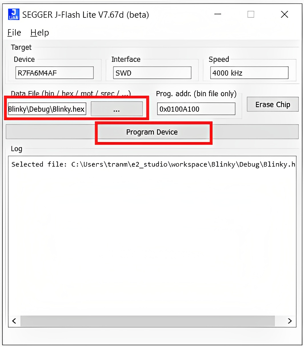
Flashing code to RA6M4 board
- Once the flashing is finished, you should see a confirmation message indicating the successful completion of the process.
- In the Source Location tab, add the newly created source directories.
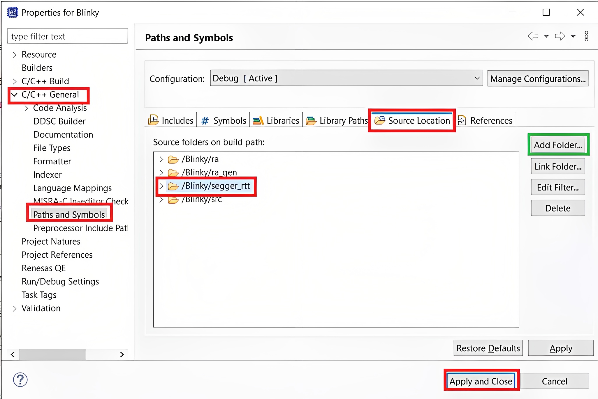
Adding source location for SEGGER
- Include the
"SEGGER_RTT.h"file in the desired file where you want to utilize debug logging.
#include "hal_data.h"
#include "SEGGER_RTT.h"
FSP_CPP_HEADER
void R_BSP_WarmStart(bsp_warm_start_event_t event);
FSP_CPP_FOOTER

/*******************************************************************************************************************//**
 * main() is generated by the RA Configuration editor and is used to generate threads if an RTOS is used.  This function
 * is called by main() when no RTOS is used.
 **********************************************************************************************************************/
void hal_entry(void)
{
    /* TODO: add your own code here */
    SEGGER_RTT_Write(0, "Hello", sizeof("Hello"));
    while(1){
        R_BSP_PinWrite((bsp_io_port_pin_t) BSP_IO_PORT_04_PIN_15, BSP_IO_LEVEL_LOW);
        R_BSP_SoftwareDelay(500, BSP_DELAY_UNITS_MILLISECONDS);
        R_BSP_PinWrite((bsp_io_port_pin_t) BSP_IO_PORT_04_PIN_15, BSP_IO_LEVEL_HIGH);
        R_BSP_SoftwareDelay(500, BSP_DELAY_UNITS_MILLISECONDS);
    }

#if BSP_TZ_SECURE_BUILD
    /* Enter non-secure code */
    R_BSP_NonSecureEnter();
#endif
}- Rebuild and flash your project, and then open the file {project_name}/Debug/{project_name}.map. Then, find the address of SEGGER_RTT
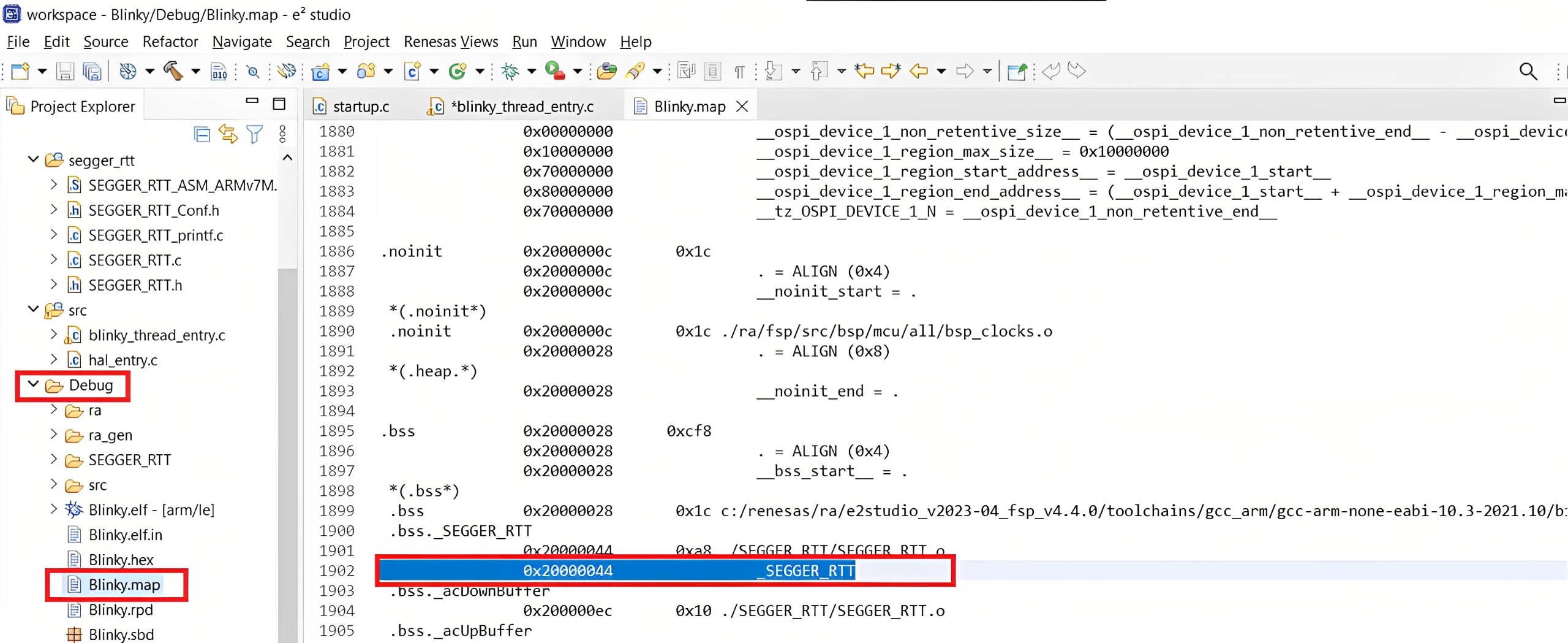
Finding the SEGGER RTT Address
- Open J-Link RTT Viewer and configure it as shown in the picture below.
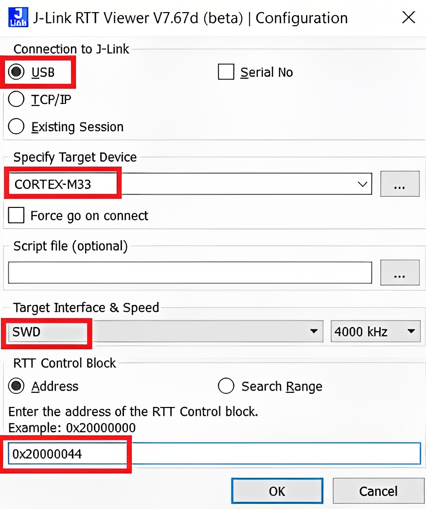
Setting up J-Link RTT Viewer
- When you click OK, it will be displayed as shown below, and you will receive logs sent from the RA6M4 board ????
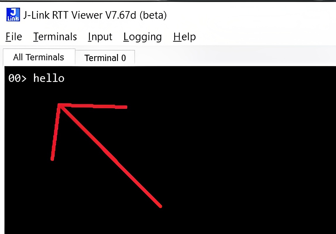
Logs retrieved successfully.
4. Conclusion
In this two-part guide, we have explored the process of getting started with the Renesas EK-RA6M4 board. In the first part, we covered the installation of software, project creation, and building. Building upon that foundation, in this second part, we delved into the crucial aspects of code flashing and debugging for the board.
By following the step-by-step instructions provided, you have learned how to flash your code to the RA6M4 board using SEGGER J-Flash Lite. Additionally, we explored the debugging capabilities of the E2 Studio debugger and the logging functionality with SEGGER J-Link RTT Viewer.
If you encounter any issues, don’t hesitate to contact us at [email protected]


[…] the next part, we’ll dive into connecting the Renesas EK-RA6M4 board to your computer, flashing code, and […]