1. Introduction
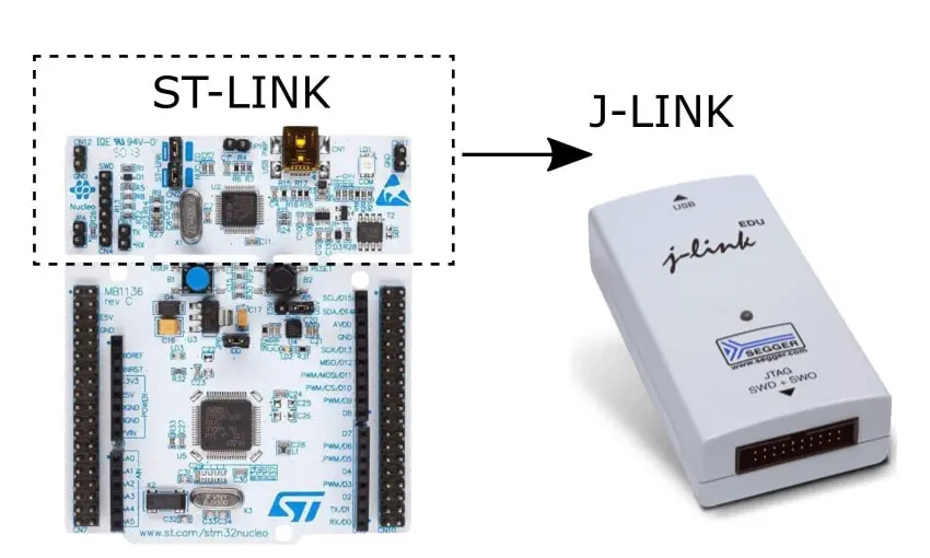
Hello everyone! You might already be familiar with the connection between STM32 microcontrollers and other devices using the ST-Link protocol. However, in certain cases, it may be necessary to use a different protocol called J-Link, depending on specific project requirements or user preferences.
Using J-Link can pose some challenges for users, particularly when it comes to STM32 microcontrollers, as it is less commonly used compared to ST-Link. In this article, our aim is to address these difficulties and provide guidance on transitioning from ST-Link to J-Link for establishing connections between STM32 and other devices.
By gaining a clear understanding of the process involved in this transition, users can make the necessary adjustments to their projects and effectively leverage J-Link for their specific needs. We will provide detailed instructions and explanations in the following sections, so please stay tuned!
2. Advantages, disadvantages of J – Link
2.1. Advantages
Flexibility and Compatibility: J-Link offers broader support for STM32 microcontrollers, including those from STMicroelectronics and other manufacturers, making it a more versatile choice compared to ST-Link
Faster Data Transmission Speed: J-Link typically provides faster data transmission speeds, enabling efficient communication between the STM32 microcontroller and external devices.
Powerful Debugging Features: J-Link offers advanced debugging capabilities, allowing users to easily view and modify registers, monitor variables, and inspect memory while the application is running. This enhances the debugging and troubleshooting process.
Robust Software: J-Link is accompanied by powerful development software that facilitates tasks such as debugging, memory read/write operations, and performance optimization. The software provides extended features for data analysis, error identification, and effective problem-solving.
2.2. Disadvantages
Higher Price: J-Link generally comes with a higher price tag compared to ST-Link and some other embedded development tools available in the market.
Compatibility Limitations: While J-Link supports a wide range of STM32 microcontrollers, there may be certain microcontroller models or versions that are not fully compatible or well-supported by J-Link.
Software Integration Limitations: J-Link requires specific accompanying software to function properly, and integrating and configuring this software can sometimes be complex, requiring in-depth knowledge of the tool and the targeted microcontroller.
Hardware Integration Limitations: J-Link necessitates a specific connector for interfacing with the STM32 microcontroller, and in certain scenarios such as accessing PCBs or in space-constrained environments, the use of extension cables may be required.
Dependency on Third-Party Software: Although J-Link is bundled with powerful development software, some advanced features and integration with specific development environments may depend on third-party software, introducing additional dependencies and considerations.
3. Setting up the necessary tools and data for J-Link
To establish J-Link communication, it is necessary to install specific environments and tools. In order to configure pins, clock frequency, and create a project for the board in STM32CubeIDE, you can refer to our previous article for detailed instructions.
Additionally, you can download the USB ST-Link driver [button size=”small” style=”primary” text=”at here” link=”http://www.st.com/en/development-tools/stsw-link009.html”]

The download link interface
Next, install the J-Link software package version 5.12b or later. You can access [button size=”small” style=”primary” text=” at here” link=”https://www.segger.com/downloads/jlink/”]to proceed with the installation.

The download link interface: software package version 5.12b
After accessing the link, you will see a user interface as shown above, and download the appropriate software package for your computer. In this case, I will download the Windows 64-bit installer.
Once the download is complete, we will have a SEGGER (JLink) folder as follows:

Folder SEGGER>>JLink
Lastly, download the SEGGER STLinkReflash utility from [button size=”small” style=”primary” text=” at here” link=”https://www.segger.com/downloads/jlink#STLink_Reflas”]

The download link interface: STLinkReflash utility
After downloading, we will have a .zip file: STLinkReflash_190812.zip
Extracting the file will result in a folder named: STLinkReflash_190812

Folder STLinkReflash_190812
4. Communicating with J-Link on NUCLEO – STM32F429ZI
In this section, we will explore the process of communicating with the STM32 using J-Link, specifically focusing on the NUCLEO – STM32F429ZI board. Step 1: Transferring the necessary SEGGER files to the project
- To begin, create a new folder within the USB_CDC project (which serves as a sample project for this example). Let’s name the folder “SEGGER_RTT.”
- Next, navigate to the SEGGER folder (located within the USB_CDC project) and access the following directories:
- The RTT folder (SEGGER\JLink\Samples\RTT\RTT)
- The Config folder (SEGGER\JLink\Samples\RTT\Config)
- Copy all the files from these two folders and paste them into the SEGGER_RTT folder within the project.

Folder SEGGER_RTT (coppied files)
Step 2: Adding Includes and Source Location for SEGGER
- Navigate to Properties / C/C++ General / Paths and Symbols / Includes. Follow the image below to add SEGGER_RTT.

Add Includes SEGGER_RTT
- Next, navigate to Properties / C/C++ General / Paths and Symbols / Source Location. Follow the image below to add the SEGGER folder.

Add Source Location SEGGER_RTT
- Finally, click on Apply and Close to save the changes.
Step 3: Modify the C source code as necessary.s
- Navigate to the main.c function and make the following edits as indicated below
      /*-------------------------------Includes SEGGER_RTT--------------------------*/
      /* Private includes ----------------------------------------------------------*/
      /* USER CODE BEGIN Includes */
      #include "SEGGER_RTT.h"
      /* USER CODE END Includes */

      ...
      /*---Perform the sending of the string "hello" using the SEGGER_RTT_Write function in main.c---*/
      int main(void)
      {
        /* USER CODE BEGIN 1 */

        /* USER CODE END 1 */

        /* MCU Configuration--------------------------------------------------------*/

        /* Reset of all peripherals, Initializes the Flash interface and the Systick. */
        HAL_Init();

        /* USER CODE BEGIN Init */

        /* USER CODE END Init */

        /* Configure the system clock */
        SystemClock_Config();

        /* USER CODE BEGIN SysInit */

        /* USER CODE END SysInit */

        /* Initialize all configured peripherals */
        MX_GPIO_Init();
        MX_ETH_Init();
        MX_USART3_UART_Init();
        MX_USB_DEVICE_Init();
        /* USER CODE BEGIN 2 */

        /* USER CODE END 2 */

        /* Infinite loop */
        /* USER CODE BEGIN WHILE */
        while (1)
        {

          /* USER CODE END WHILE */
      	  SEGGER_RTT_Write(1,"hello",5);
          /* USER CODE BEGIN 3 */
        }
        /* USER CODE END 3 */
      }
- Function SEGGER_RTT_Write()
    /*--------------------Function SEGGER_RTT_Write()----------------------------------
    *       SEGGER_RTT_Write
    *
    *  Function description
    *    Stores a specified number of characters in SEGGER RTT
    *    control block which is then read by the host.
    *
    *  Parameters
    *    BufferIndex  Index of "Up"-buffer to be used (e.g. 0 for "Terminal").
    *    pBuffer      Pointer to character array. Does not need to point to a \0 terminated string.
    *    NumBytes     Number of bytes to be stored in the SEGGER RTT control block.
    *
    *  Return value
    *    Number of bytes which have been stored in the "Up"-buffer.
    *
    *  Notes
    *    (1) Data is stored according to buffer flags.
    */
    unsigned SEGGER_RTT_Write(unsigned BufferIndex, const void* pBuffer, unsigned NumBytes) {
      unsigned Status;

      INIT();
      SEGGER_RTT_LOCK();
      Status = SEGGER_RTT_WriteNoLock(BufferIndex, pBuffer, NumBytes);  // Call the non-locking write function
      SEGGER_RTT_UNLOCK();
      return Status;
    }
- Finally, proceed to build the code

Build Finished
Step 4: Connect the NUCLEO – STM32F429ZI board to your computer or laptop

Connect board to computer

Check Port in Device Manager
- Currently, the communication between the board and the laptop is established using the ST-Link protocol. To switch from ST-Link to J-Link, follow these steps:
- Open the STLinkReflash_190812 folder.
- Locate and run the STLinkReflash.exe file.
- Follow the steps illustrated in the images below to perform the conversion process.


- Finally, select ‘1’: Upgrade to J-Link.
- Next, run the J-Link RTT Viewer V7.67d (beta) tool.

Interface J-Link RTT Viewer
- To obtain the address, follow these steps while building the code in STM32CubeIDE:
- Open the USB_CDC.map (Debug) file.
- Retrieve the address as shown in the figure below.

Recieve the address
- After completing the process, click on the “Decline” button. You will then see the “hello” string displayed on the Terminal, just like before

Decline and Finish
- By following these steps, you have successfully connected the STM32 board to your laptop using J-Link.
NOTE: After transitioning to J-Link, your NUCLEO-STM32F429ZI board is now utilizing J-Link for communication. In certain scenarios, such as programming the code with STM32CubeProgrammer, reverting back to ST-Link may be necessary. If you come across this situation, you will need to switch back from J-Link to ST-Link.
- Due to the use of J-Link instead of J-Link Pro, this error commonly occurs. Here is a solution to address this issue by utilizing J-Flash Lite.

Error getting LOG using SEGGER J-Flash: License error
- So here are the steps to help you get LOG using SEGGER J-Flash Lite

Config Device and Interface

Select file .bin and Flashcode

Select Accept

Flashed Done
- To complete the log retrieval process, follow the steps outlined above using J – Link RTT Viewer.

Finished get log
5. Conclusion
In conclusion, this article has aimed to provide you with a comprehensive understanding of configuring J-Link for communication between STM32 and other devices. You have also gained valuable insights into the advantages and disadvantages of J-Link compared to ST-Link, equipping you to utilize it effectively based on your specific requirements.
We wish you every success in your future endeavors.


