1. Overview
2. Creating the Example Project
2.1. Downloading and Installing Software and Development Tools
2.2. Creating a Blink LED Project
2.3. Modifying, Generating, and Building the Blink LED Project
3. Conclusion
1. Overview
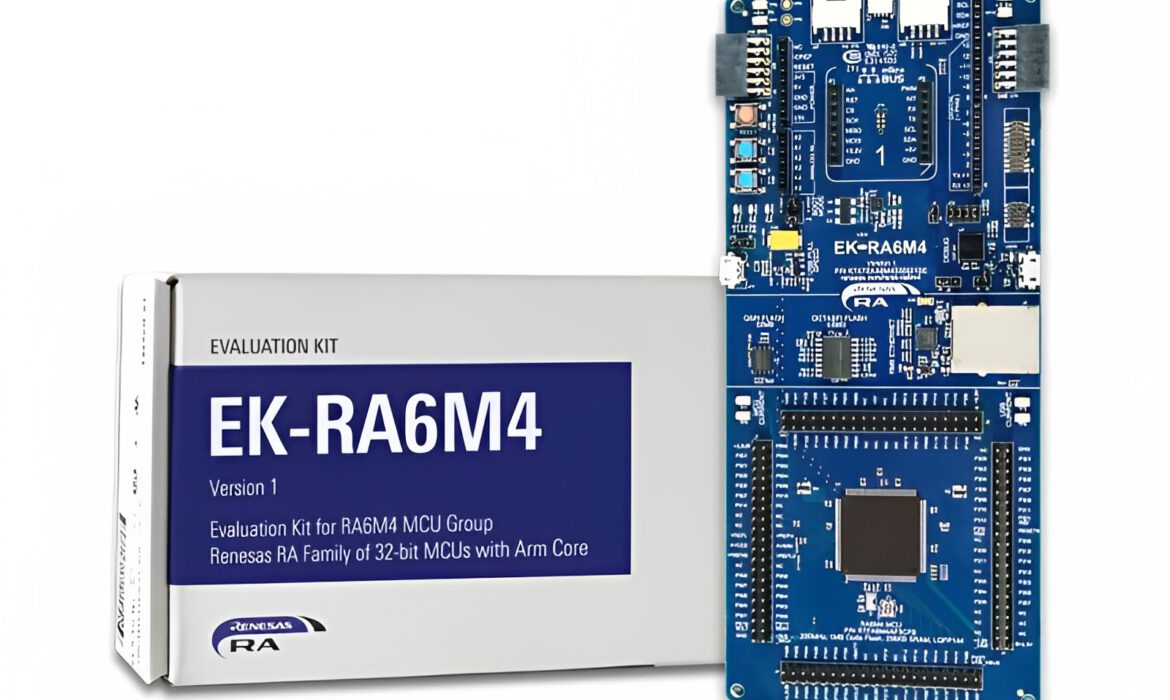
The Renesas EK-RA6M4 Evaluation Kit for the RA6M4 MCU Group offers users a seamless and efficient way to evaluate the extensive features of the RA6M4 MCU group and develop high-performance embedded systems applications. With the integrated Flexible Software Package (FSP) and e2 studio IDE, users can effortlessly harness the full potential of the Renesas EK-RA6M4. This versatile kit provides a wide range of on-board features, empowering users to bring their innovative ideas to life by seamlessly integrating with popular ecosystem add-ons of their choice
The key features of the EK-RA6M4 board are categorized into three groups, consistent with the kit’s architecture. These groups include the following:
- R7FA6M4AF3CFB MCU (referred to as RA MCU)
- 200 MHz, Arm® Cortex®-M33 core
- 1 MB Code Flash, 256 kB SRAM
- 144 pins, LQFP package
- Native pin access through 4 x 40-pin male headers
- MCU current measurement points for precision current consumption measurement
- Multiple clock sources – RA MCU oscillator and sub-clock oscillator crystals, providing precision 24.000 MHz and 32,768 Hz reference clock. Additional low-precision clocks are available internal to the RA MCU.
System Control and Ecosystem Access
- USB Full Speed Host and Device (micro AB connector)
- Three 5 V input sources
- Three Debug modes
- User LEDs and buttons
- Five most popular ecosystems expansions
- MCU boot configuration jumper
Special Feature Access
- Ethernet (RJ45 RMII interface)
- 64 MB (512 Mb) External Octo-SPI Flash
- 32 MB (256 Mb) External Quad-SPI Flash
Discover the Top Side of the EK-RA6M4 Board and Gain Insight into Its Components:
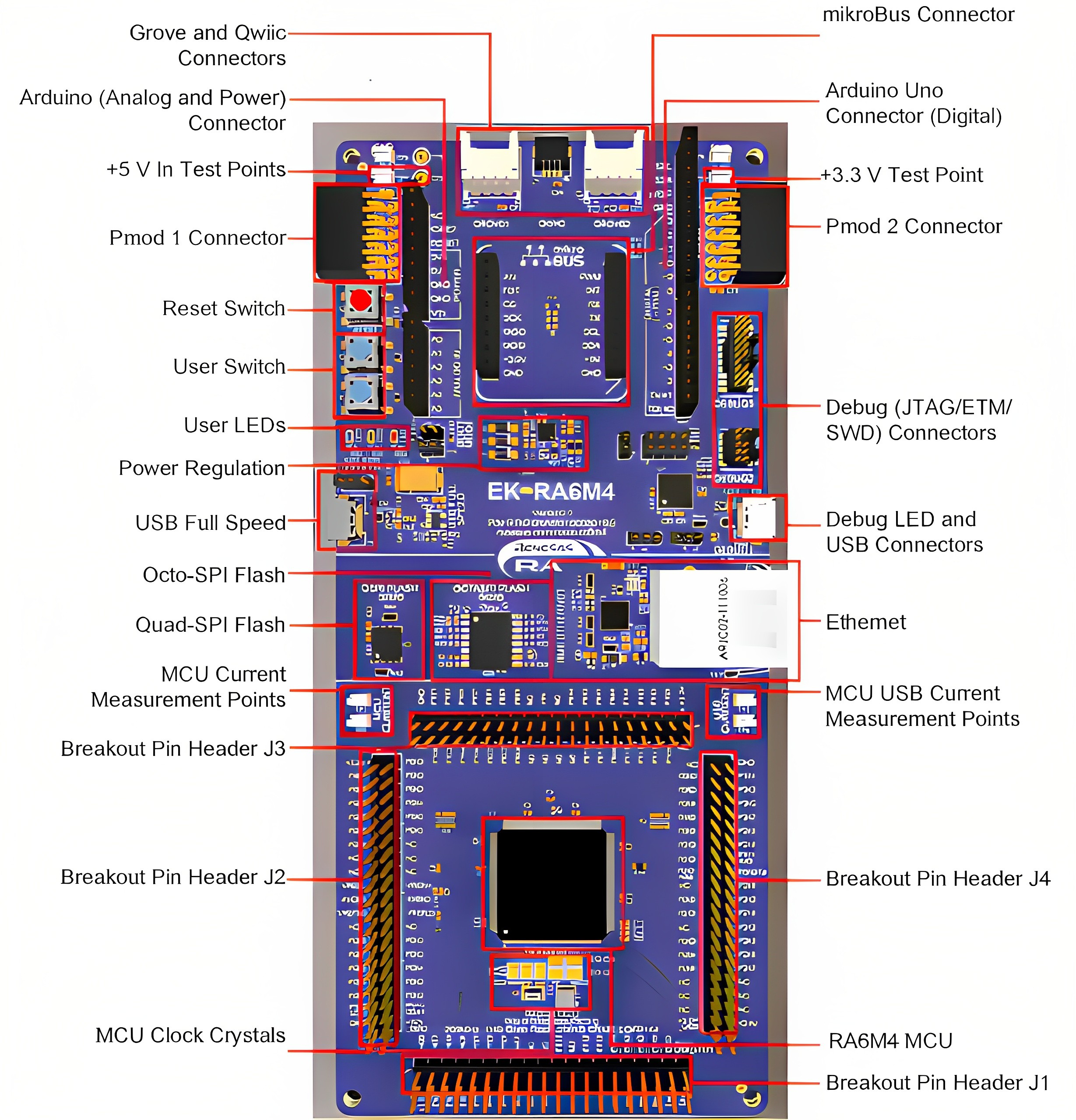
EK-RA6M4 Board Top Side
The Bottom Side of the EK-RA6M4 Board:
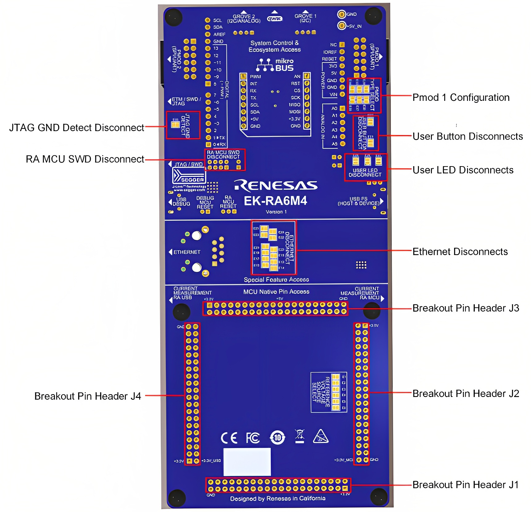
EK-RA6M4 Board Bottom Side
2. Creating the Example Project
Hardware Requirements
- EK-RA6M4 board
- Micro USB device cable
- A PC with at least 1 USB port
Software Requirements
- Windows® operating system
- e2 Studio IDE
- SEGGER J-Link® USB drivers
- Flexible Software Package
2.1. Downloading and Installing Software and Development Tools
Before creating an example project, it is essential to download and install the necessary software and development tools on your PC. I highly recommend downloading the Flexible Software Package (FSP) from the Download Link.
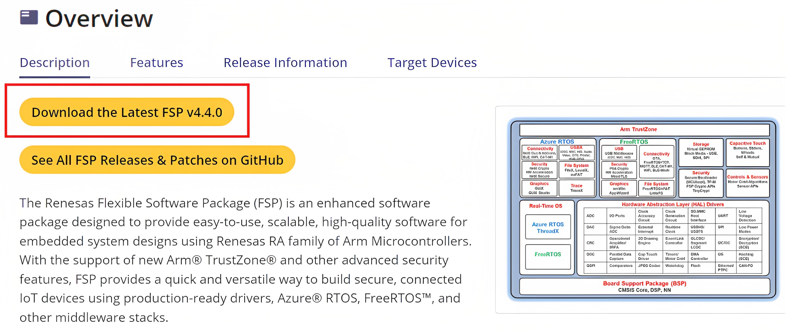
Download the FSP
To initiate the automatic download of the Flexible Software Package (FSP), please complete the necessary fields in the form and proceed with its submission.

Complete Form
After downloading the file, simply double-click on the installer file (setup_fsp_vX_X_X.exe) to start the e2 studio installation process.
If prompted to select users for installation, choose “All users” for optimal results.
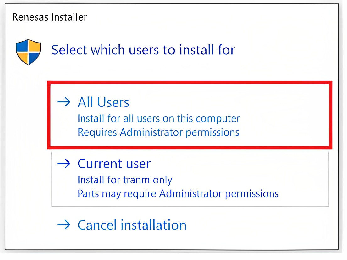
Select users to install for
When prompted to select the installation type, choose “Custom Install” for improved flexibility. Then, proceed by clicking “Next” to continue
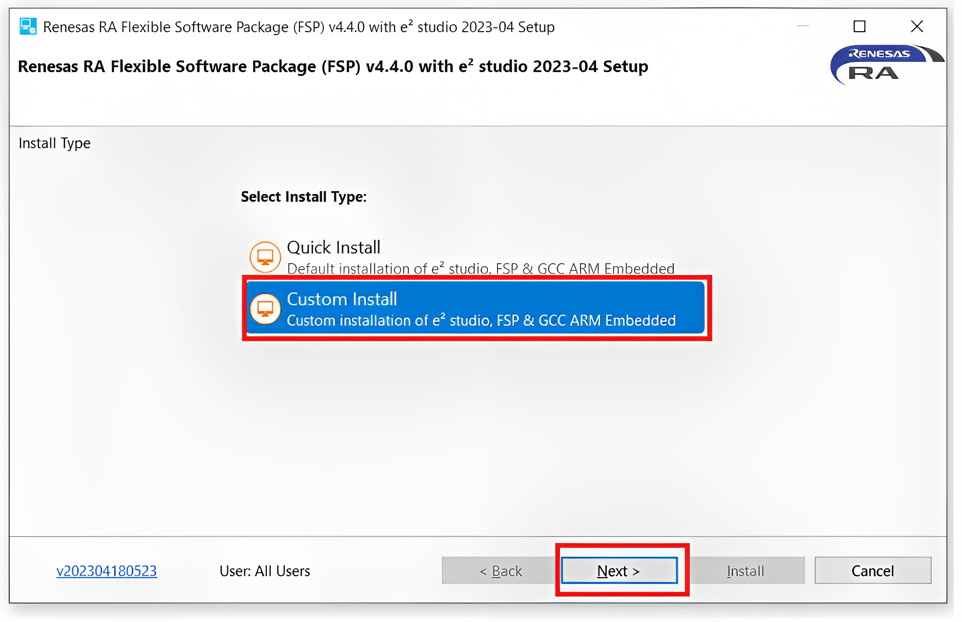
Choose the installation type
In the “Welcome” step, please wait while the installer checks some configurations. After the process is complete, click “Next” to proceed.
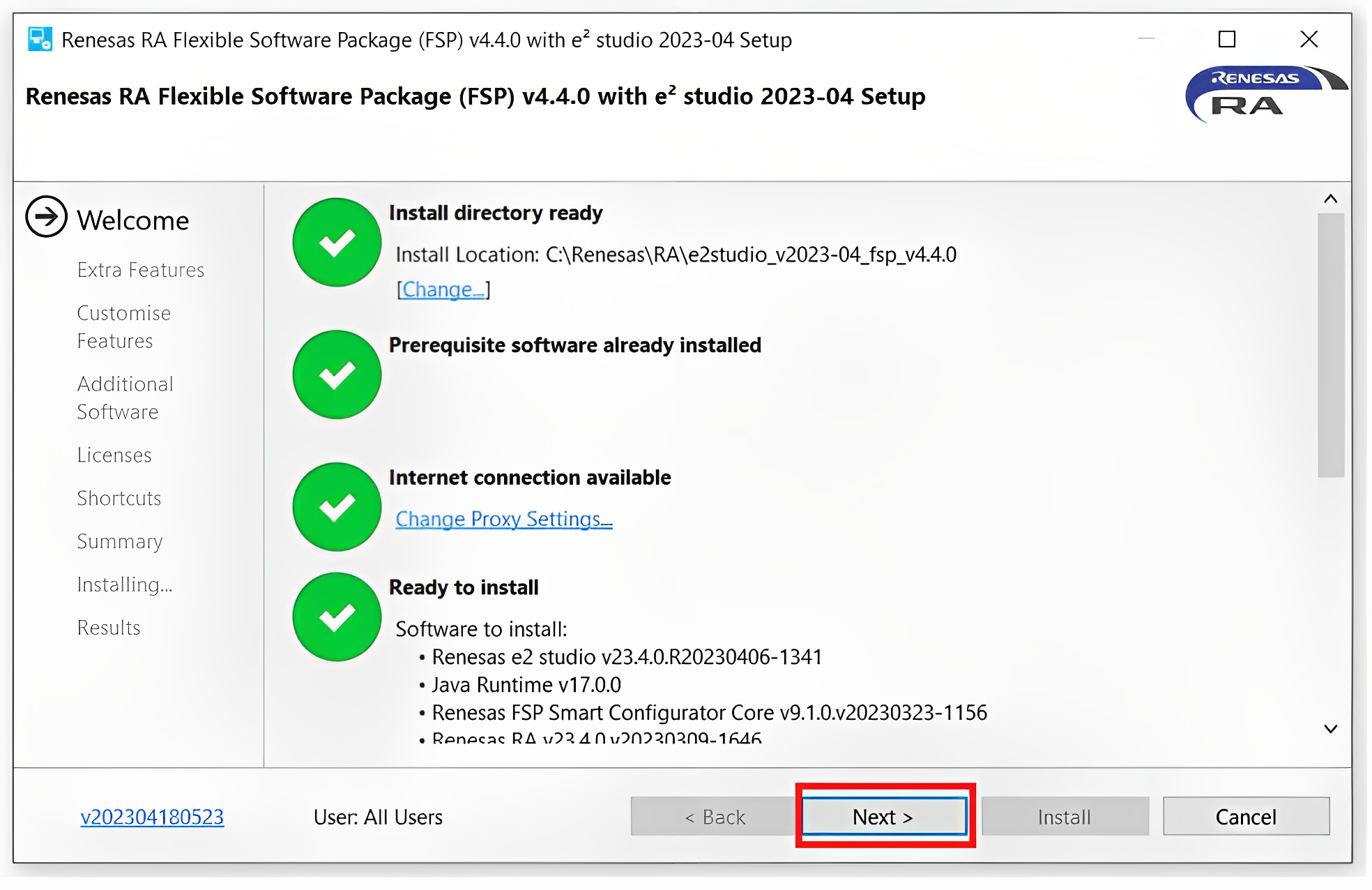
The installation’s “Welcome” step.
Follow the default settings for the remaining installation steps
After the installation is successfully completed, it will be displayed as shown. Simply click “OK” to finalize the installation process.
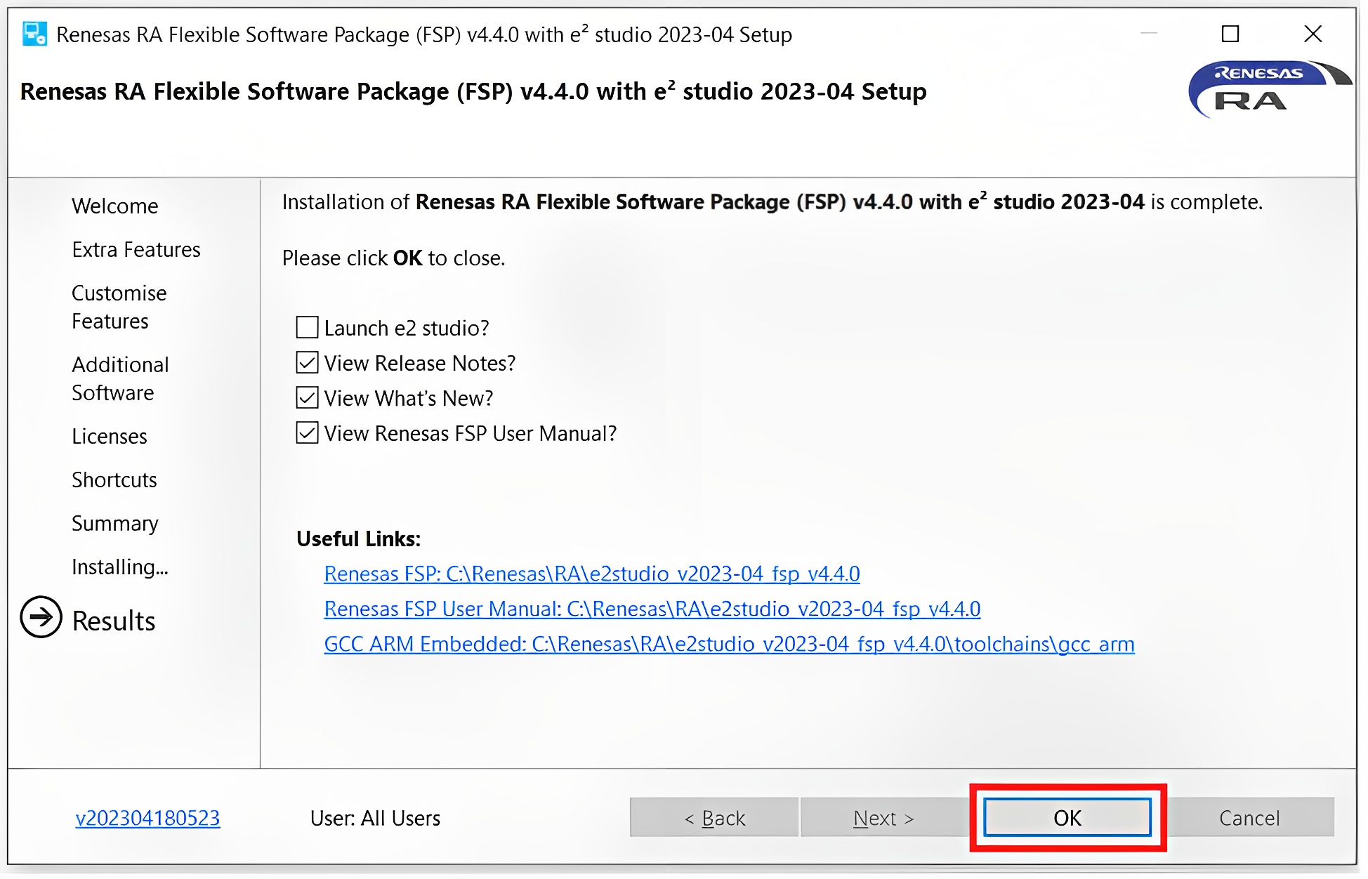
Complete the installation
2.2. Create a Blink LED project
Now that you have installed the software and development tools, let’s create a simple project to make the LED on the EK-RA6M4 board blink:
- Launch e2 studio
- Browse to the Workspace where the project file is to be imported. Enter the name in the Workspace
dialog box to create a new workspace.
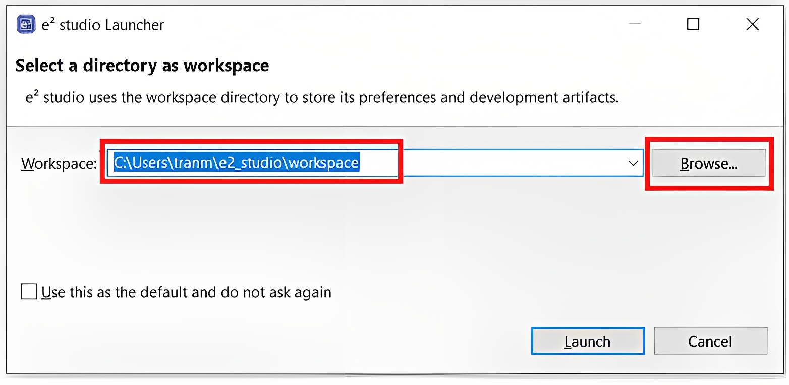
Creating a New Workspace
- Click Launch.
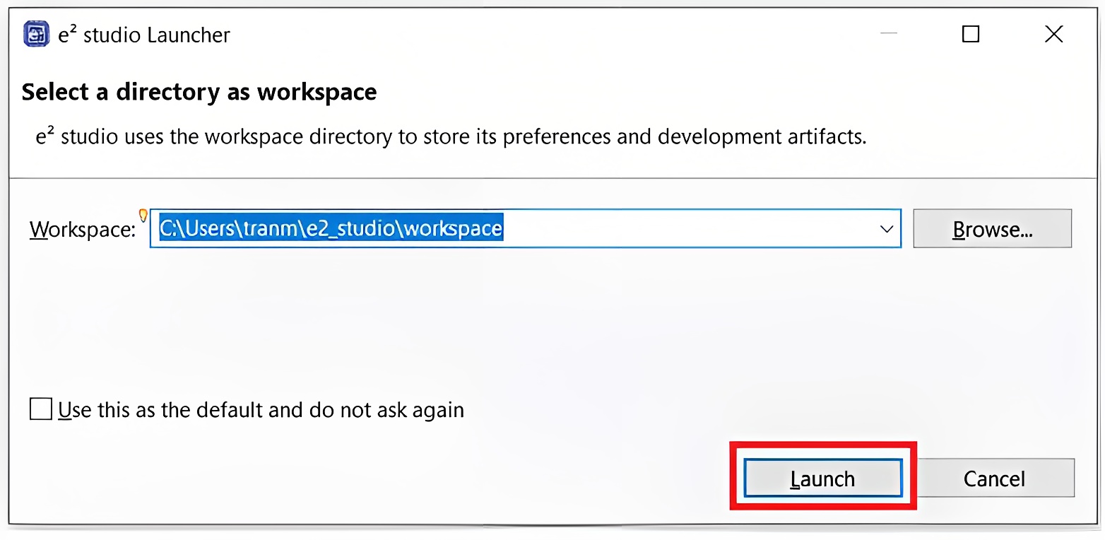
Launching the Workspace
- Click New from the File drop-down menu. Then select Renesas C/C++ Project > Renesas RA
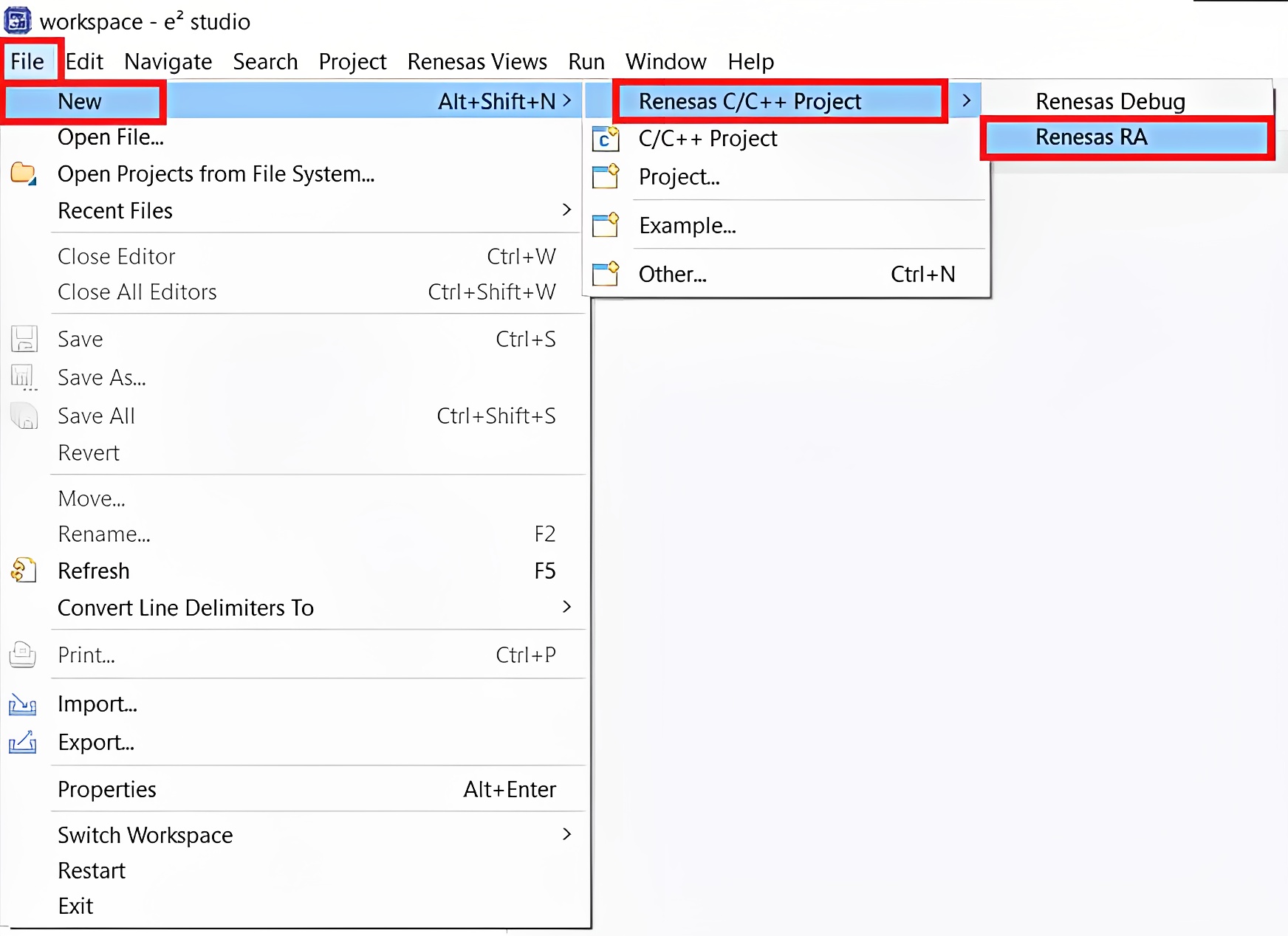
Creating the Project
- In the New C/C++ Project dialog box, select Renesas RA C/C++ Project and click Next
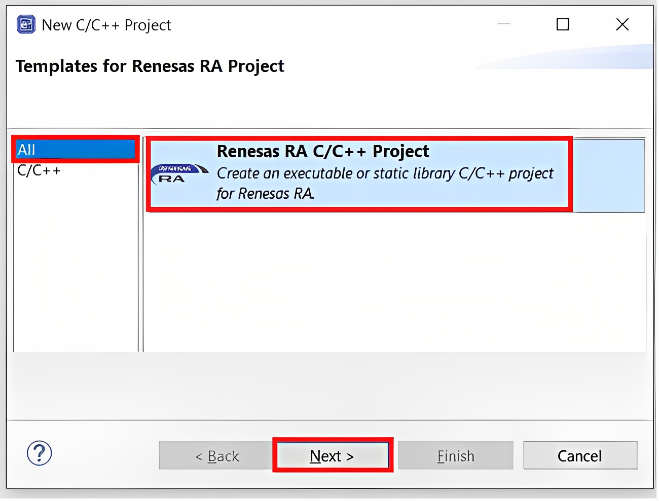
Templates for RA Project
- In the Project Name and Location dialog box, enter the Project name and click Next
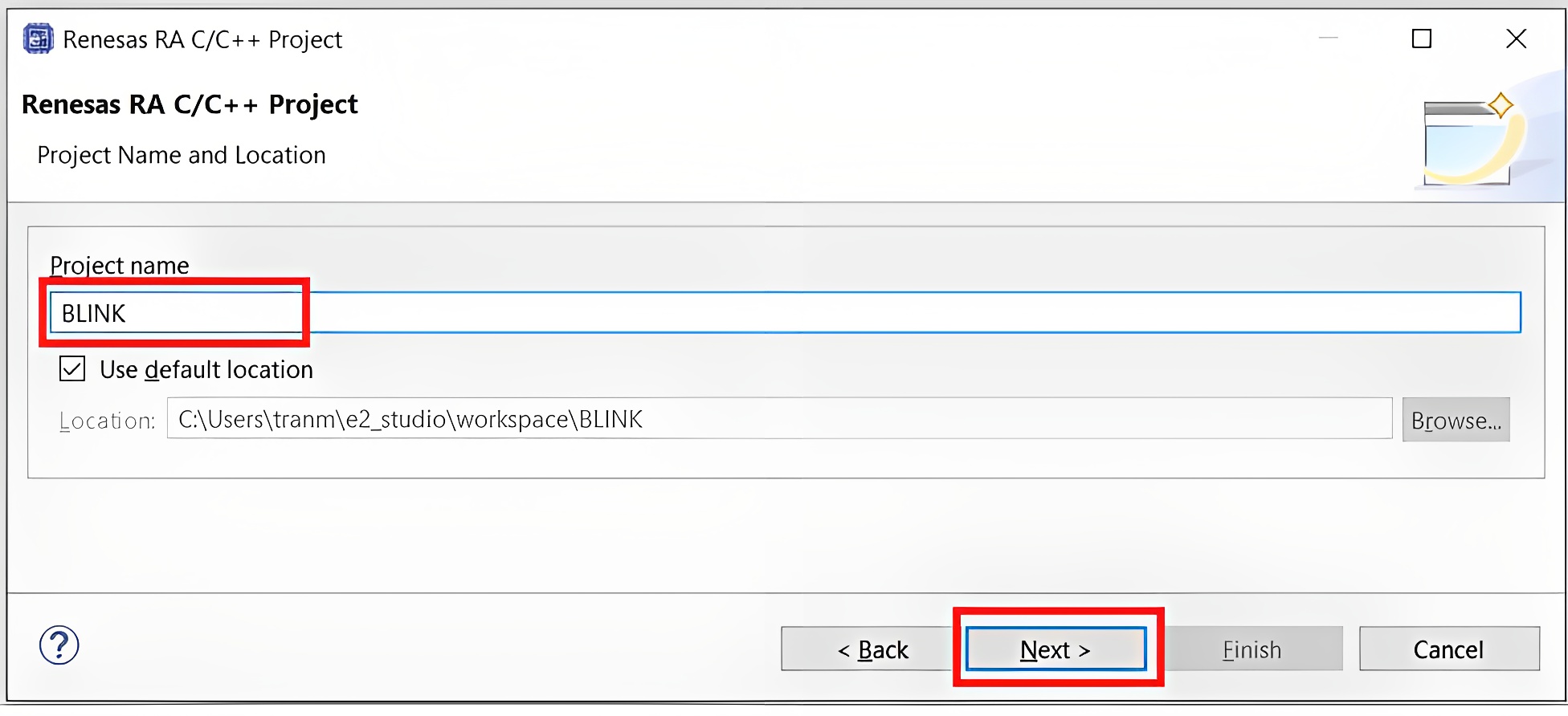
Enter Project name
- Within the Device and Tools Selection dialog box, make use of the GNU ARM Embedded Toolchains and the J-Link ARM Debugger
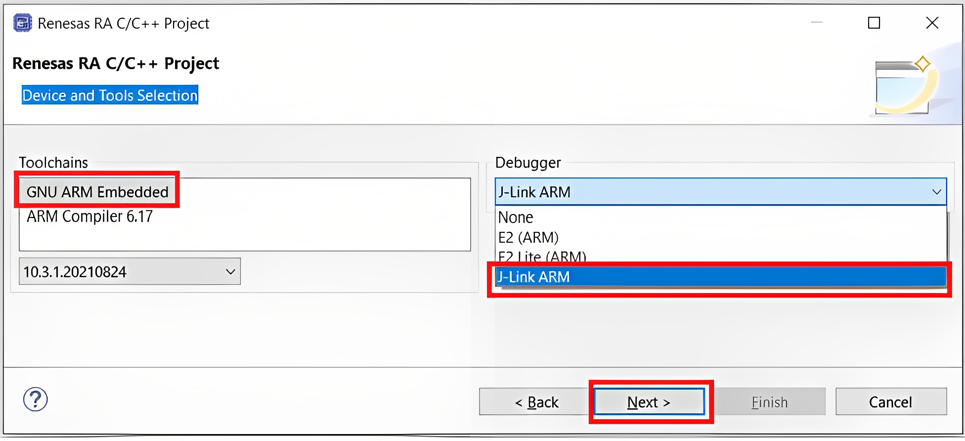
Device and Tools Selection
- In the Build Artifact and RTOS Selection dialog box, select Executable and FreeRTOS (optional) and click Next
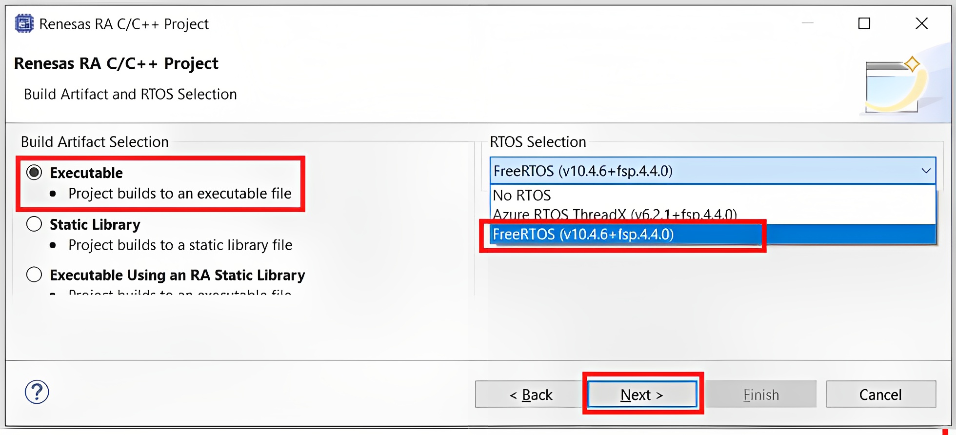
Build Artifact and RTOS Selection
2.3. Modifying, Generating, and Building the BLINK Project
- Once the BLINK Project is created, click the configuration.xml file to open the configurator. The configurator provides an easy-to-use interface to configure the properties of the MCU peripherals.
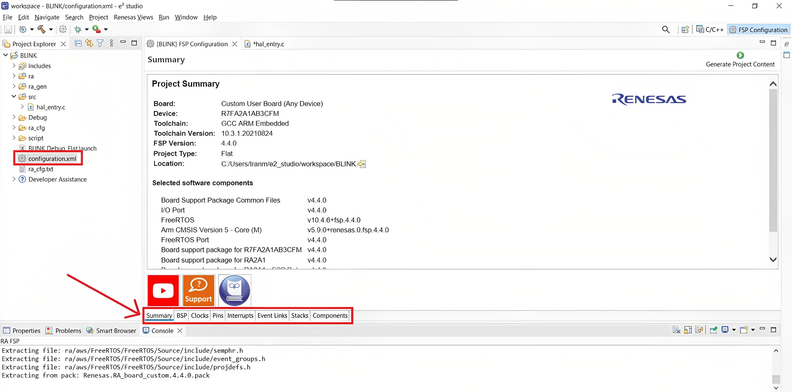
Opening the Configurator
- Click on the BSP tag, and enter the Board and Device. We utilize the Renesas EK-RA6M4 board, so please enter EK-RA6M4 and R7FA6M4AF3CFB respectively
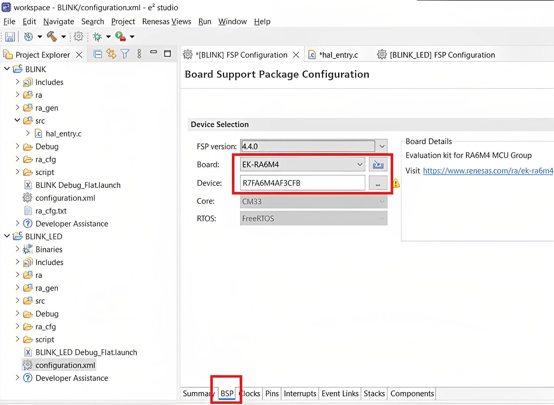
Board Support Package Configuration
- 5 LEDs are provided on the EK-RA6M4 board. The behavior of the LEDs on the EK-RA6M4 board is described in the following table. To initiate the blinking of LED1, which is assigned to P415 (Port 4 – Pin 15), it is necessary to configure the corresponding pin.

EK-RA6M4 Board LED Functions
- Click on the PINS tag and navigate to the Pin Selection column. Locate and click on P415. In the Pin Configuration column, select Output mode (Initial Low) as the desired mode.
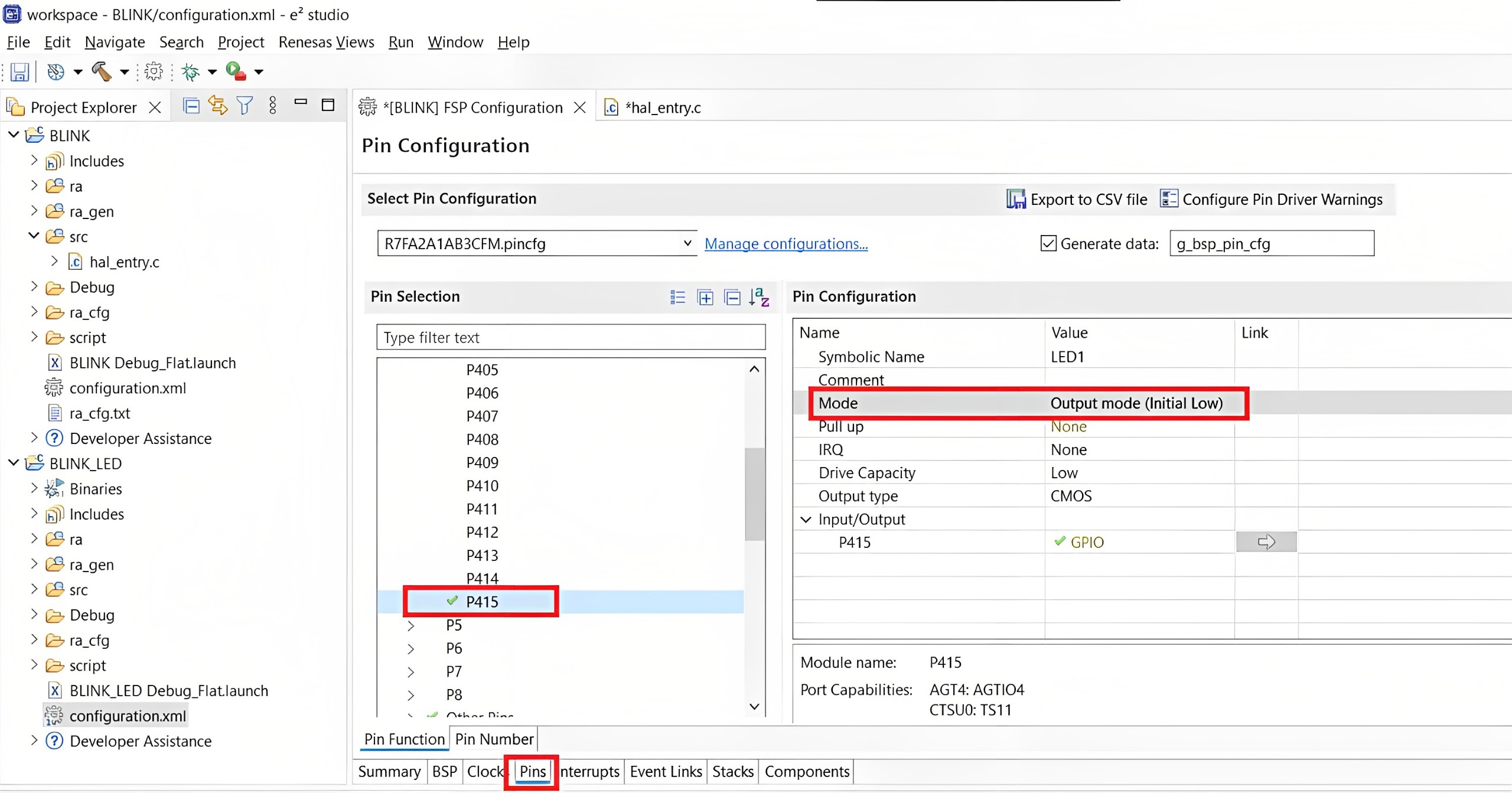
Pin Configuration
- Now, generate the code by clicking on Generate Project Content. A dialog box may appear with an option of saving the configuration changes. Click Proceed.
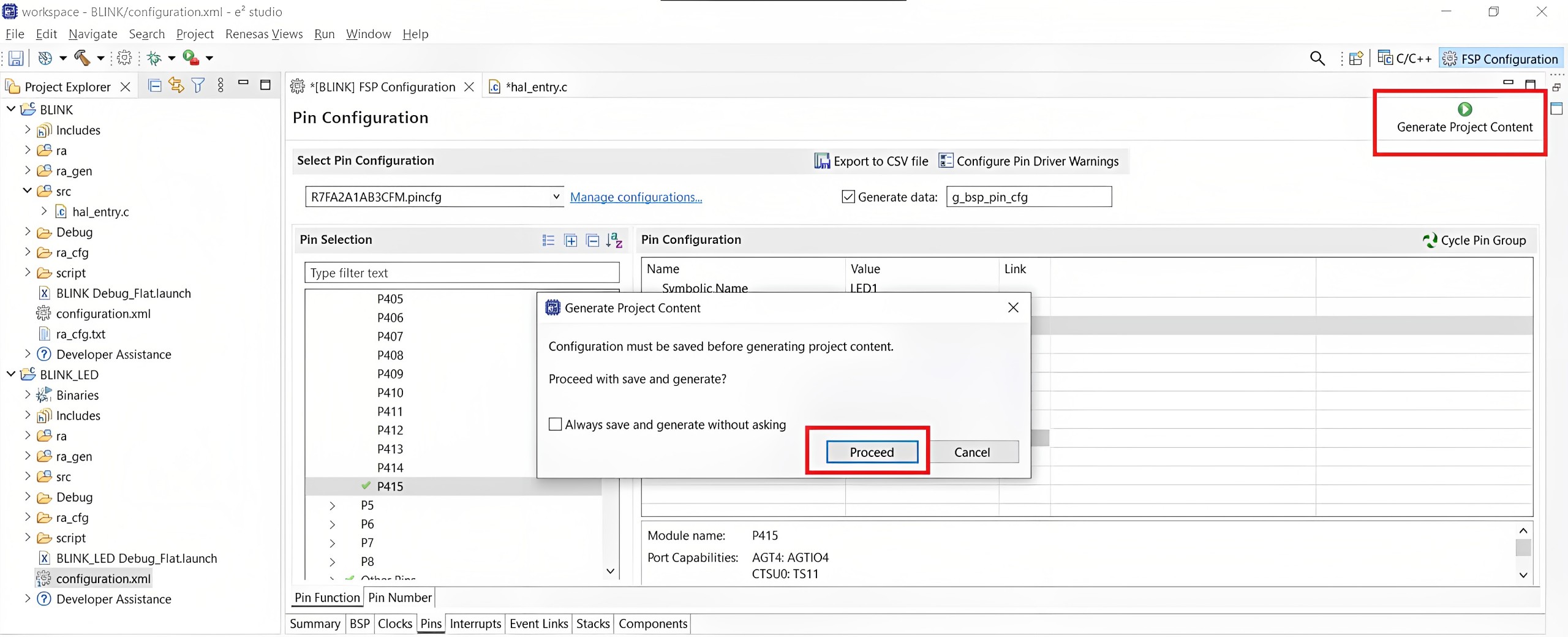
Generating Project Content
- Modify the hal_entry.c source files in the /src folder as needed and save the changes
#include "hal_data.h"
FSP_CPP_HEADER
void R_BSP_WarmStart(bsp_warm_start_event_t event);
FSP_CPP_FOOTER

/*******************************************************************************************************************//**
 * main() is generated by the RA Configuration editor and is used to generate threads if an RTOS is used.  This function
 * is called by main() when no RTOS is used.
 **********************************************************************************************************************/
void hal_entry(void)
{
    /* TODO: add your own code here */
    while(1){
        R_BSP_PinWrite((bsp_io_port_pin_t) BSP_IO_PORT_04_PIN_15, BSP_IO_LEVEL_LOW);
        R_BSP_SoftwareDelay(500, BSP_DELAY_UNITS_MILLISECONDS);
        R_BSP_PinWrite((bsp_io_port_pin_t) BSP_IO_PORT_04_PIN_15, BSP_IO_LEVEL_HIGH);
        R_BSP_SoftwareDelay(500, BSP_DELAY_UNITS_MILLISECONDS);
    }

#if BSP_TZ_SECURE_BUILD
    /* Enter non-secure code */
    R_BSP_NonSecureEnter();
#endif
}- Build the project by clicking the Build icon.
Build the project
- A successful build produces an output as follows:

Successful Build Output
3. Conclusion
In this part, we covered the essential steps to get started with the Renesas EK-RA6M4 board, including software installation, project creation, configuration, and building the project.
In the next part, we’ll dive into connecting the Renesas EK-RA6M4 board to your computer, flashing code, and debugging. These steps are crucial for running and testing your projects effectively. We’ll provide clear guidance and practical examples to ensure a smooth experience with the Renesas EK-RA6M4 board.
If you encounter any issues, don’t hesitate to contact us at [email protected]





[…] into the essential steps of flashing, debugging, and logging for the Renesas RA6M4 board. In the previous part, we covered the installation of necessary software and the process of project creation and […]